Categories: Microcontroller circuits
Number of views: 32016
Comments on the article: 0
Most popular sensors for Arduino
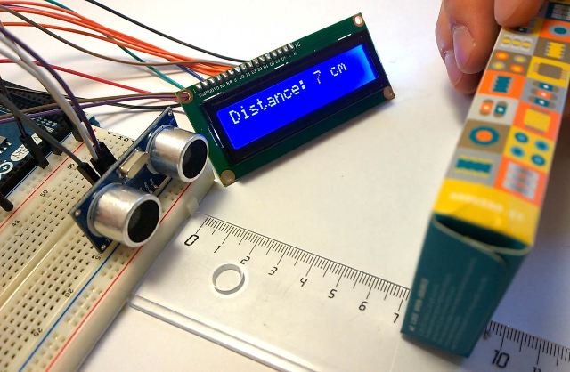
Sensors are used in a wide variety of circuits and projects. No automation can do without them. We are interested in them because a project has been created to simplify the design and popularization of electronics Arduino. This is a finished board with a microcontroller and everything you need to work with it and program it. In this article, we will consider sensors for Arduino, but they can also be used with other microcontrollers.
What are the sensors?
Sensors are the eyes, ears and other senses microcontroller or other control device. They are distinguished by the nature of the signal and by purpose.
By the nature of the signal is divided into:
-
Analogue;
-
Digital
And for the purpose, the sensors are for measuring:
-
Temperature;
-
Pressure;
-
Humidity
-
Acidity;
-
Illumination
-
Water level or other substances;
-
Vibration
-
And other specialized components.
If we talk about Arduino, then, when receiving information from sensors, we process a digital signal, or measure the voltage from the analog output of the module. As already mentioned, sensors are digital and analog. Some modules for Arduino have both digital and analog output, which unifies them.
By device they are
-
Resistive
-
Inductive
-
Capacitive;
-
Piezoelectric;
-
Photocells and other types.
Light or light sensor
The easiest way to determine the brightness of something - use a photoresistor, photodiode or phototransistor. You can connect one of the listed options to Arduino or buy a special board - light sensor.
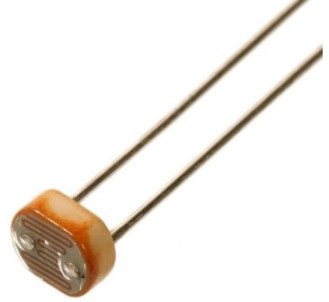
What are the benefits of a turnkey solution? Firstly, to determine the changes in the illumination of one photocell is not enough, you also need a regular or tuning resistor, maybe it comparator, for stepwise yes / no operation. Secondly, a factory-made printed circuit board will be more reliable than a hinged mounting or a batch board, or other ways that amateurs use.
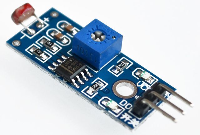
On aliexpress or in other online stores it can be found on request "PHOTOSENSITIVE-SENSOR" or simply "light sensor".
This module has three outputs:
-
Nutrition;
-
Land;
-
Digital output from the comparator.
Or a four-pin version:
-
Nutrition;
-
Land;
-
Digital output from the comparator;
-
Analogue
So on the board placed tuning resistor to adjust the timing of the comparator can produce a digital signal.
Examples of using:
-
Light sensor for photo relay;
-
Alarm (paired with the emitter);
-
Counter of objects that cross the light beam, etc.
It is difficult to achieve exact values, since a correct light meter will be needed for the correct adjustment by illumination. Photoresistors are more suitable for determining abstract values such as "dark or light."
In addition to such a board on sale, you can find quite interesting GY-302 module. This is a light sensor based on the BH-1750 integrated circuit. Its feature is that it is a digital module, it has a capacity of 16 bits, communicates with microcontrollers via the i2c bus. 16 bits allow you to measure illumination from 1 to 65356 Lux (Lx).
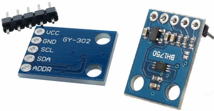
Below is a diagram of its connection. You may notice that SDA and SCL connected to the analog pins of the microcontroller.
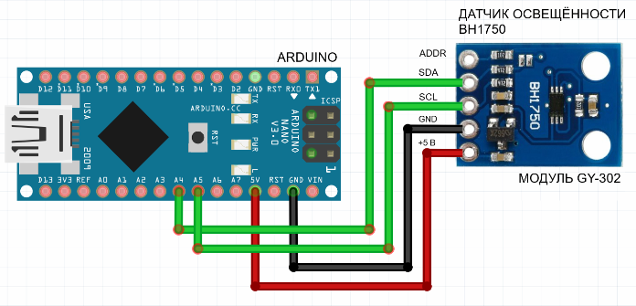
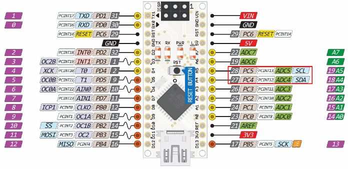
This is due to the fact that the I2C bus is implemented on these arduino pins, which can be seen by looking at the following picture. Therefore, do not be fooled by this fact; the sensor is digital.
The advantage of digital sensors is that you do not need to check the values of each instance, compile tables to translate the measured values into real scales and so on.In most cases, for digital sensors, it is enough to simply connect a ready-made library and read the values converted into real units.
Example sketch for GY-302 (BH-1750):
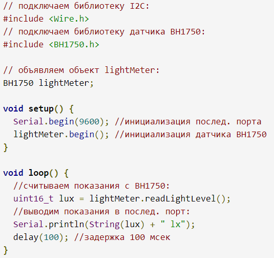
How does a sketch work?
At the beginning, we tell the program that we need to connect the Wire.h library, which is responsible for communication via the I2C line, and the BH1750. The rest of the actions are well described in the comments, and as a result, every 100ms we read the value from the sensor in Lux.
Characteristics of GY-302 BH1750:
-
I2C microcontroller communication
-
Spectral response similar to eye sensitivity
-
Errors due to infrared radiation are minimized
-
Measuring Range 0-65535 Lux
-
Supply voltage: 3-5 V
-
Low current consumption and sleep function
-
50/60 Hz light noise filtering
-
The maximum number of sensors on 1 I2C bus is 2 pieces.
-
No calibration required
-
Current consumption - 120 μA
-
In sleep mode - 0.01 μA
-
Measured wavelength - 560 nm
-
In high resolution mode - 1 Lux
-
In low resolution mode - 4 Lux
-
ADC - 16 bit
Time taken for measurements:
-
In high resolution mode - 120 ms
-
In low resolution mode - 16 ms
Obstacle sensor
I chose this sensor as the next one to consider, because one of its options works on the basis of a photodiode or phototransistor, which are similar in principle to the photoresistor discussed in the previous section.
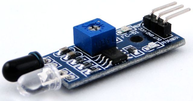
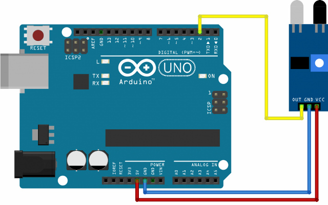
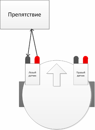
Its name is "optical obstacle sensor." The main functional element is the photodiode and LED emitting and receiving in the IR spectrum (therefore, not visible to the human eye, as well as a threshold assembly assembled, for example, on a comparator with a sensitivity regulator. Using it, the distance at which the sensor is triggered is adjusted, by the way it is digital.
Connection diagram example:
An example of a signal processing program from a sensor.
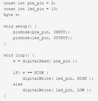
Here, if the output from the sensor is “1”, which means “there is an obstacle”, the LED on the Arduino board or connected to the 13th pin (the same thing) will light up. Most often used in robotics and alarms.
Distance sensor
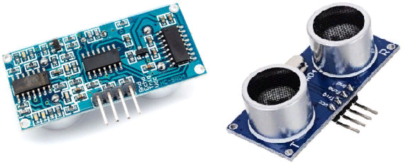
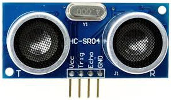
The previous copy consists of a receiver, - a photodiode, and an emitter, - an LED. The ultrasonic distance sensor also consists of a receiver and an emitter of ultrasonic waves. His name - HC SR04.
Characteristics HC SR04:
-
5V supply voltage
-
The operating parameter of the force t oka - 15 mA
-
Passive current <2 mA
-
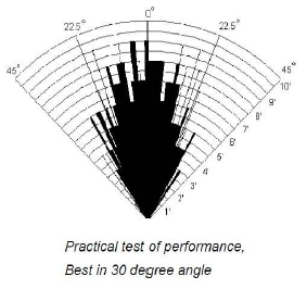
Viewing angle - 15 °
-
Touch Resolution - 0.3 cm
-
Measuring angle - 30 °
-
Pulse Width - 10-6 s
-
Measurement range: 2-400 cm.
The error appears due to:
-
temperature and humidity - can be reduced by measuring the temperature with DHT-11 or DHT-22, for example, and entering coefficients to correct the measurements.
-
distance to the object;
-
the location of the object relative to the sensor (according to the radiation diagram) can be offset by installing HC SR04 on the servo to change direction and make accurate adjustments.
-
performance quality of the sensor module elements.
Radiation pattern:
The board has four outputs:
-
VCC - power;
-
Trig - input signal;
-
Echo - output signal;
-
GND is a common wire.
How to process readings?
1. We send a pulse with a duration of 10 μs to the TRIG input;
2. Inside the module, the pulse is converted into a pack of 8 pulses that follow each other with a frequency of 40 kHz and are sent through the emitter;
3. Impulses reflected from the obstacle arrive at the receiver and are output to ECHO;
4. The duration of the pulse received from the ECHO output should be divided by 58.2 to get the distance in centimeters and by 148 if you need to convert to inches.
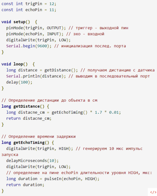
Example code:
Measure temperature
The easiest way to measure temperature using a microcontroller is use a thermocouple or thermistor. Thermocouples are used to measure high temperatures, to measure indoor and outdoor - the one that I will talk about a bit below will do, but for now, let's look at a thermocouple.
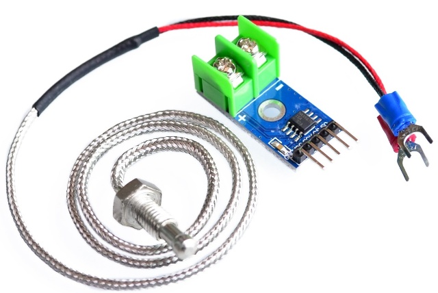
Each type of thermocouple has its own approach for working with a microcontroller. For example, there is a K-type thermocouple, or as it is also called - chromel-alumel, with a range of measured temperatures from -200 to +1400 degrees Celsius with a sensitivity of 41 mV / degree Celsius. And for her there is a special converter based on the IC max6675, it has a function for compensating the temperature of the cold junction and so on.
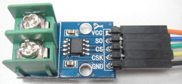
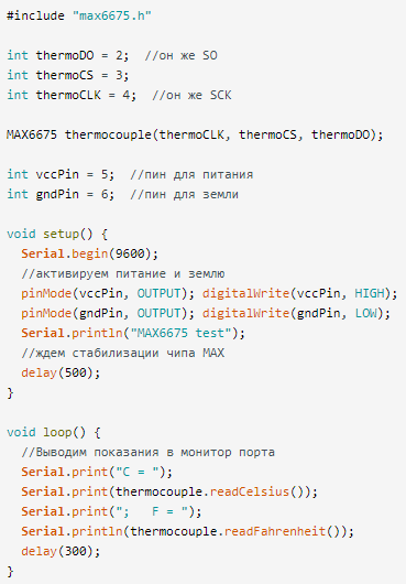
You can work with this module using the library of the same name for Arduino. In the figure below you see an example of program code for this case.
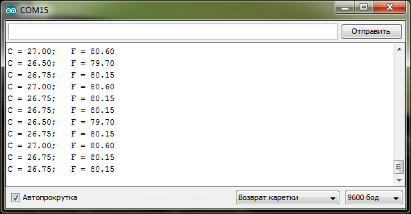
Then the following is displayed on the serial port monitor.
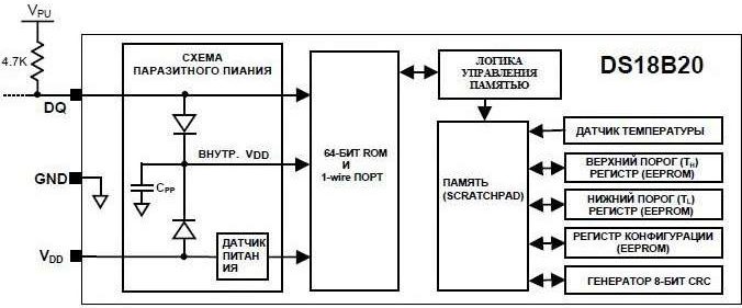
But there is also a digital temperature sensor DS12B20, it can be called classic, since it has been used for many years in amateur projects, and long before the appearance of Arduino.
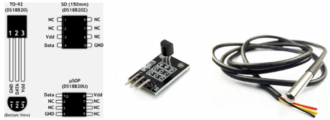
This digital integrated circuit its internal device is shown in the figure below:
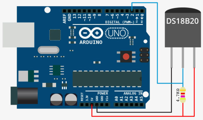
Board connection diagram:
Key Features and Information DS18b20:
-
The error is less than 0.5 ° C (in the temperature range from -10 ° C to + 85 ° C).
-
No calibration required
-
Measurement range - from -55 С to + 125С
-
VCC, supply voltage 3.3-5V.
-
resolution up to 0.0625С, set by software;
-
Resolution - 12 bits
-
Each instance is assigned a unique serial code. This is necessary in order to easily use several pieces in one project
-
Communication Interface - 1-Wire
-
No strapping required
-
The maximum number of sensors on one line is 127 pieces.
-
Spurious power mode - in this case, the sensor is powered directly from the communication line. At the same time, a temperature measurement higher than 100C is not guaranteed
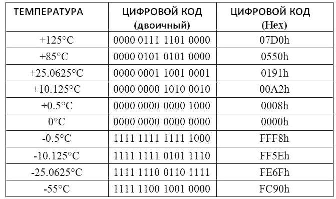
Below you see the conversion chart of the binary code from DS18b20 to temperature in degrees Celsius.
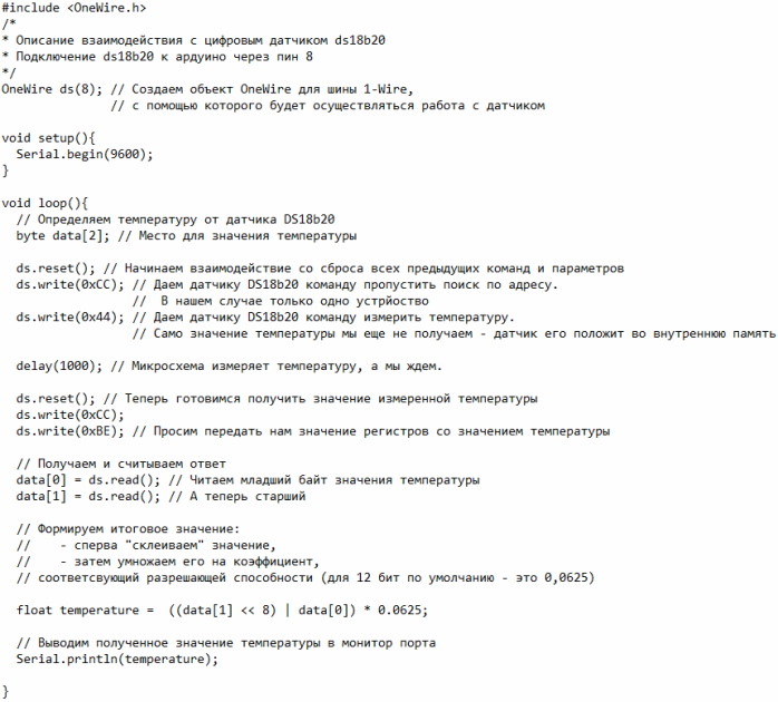
Example program for reading temperature values.
Atmospheric pressure sensors
Electronic barometers are assembled on the basis of atmospheric pressure sensors. The following options were widely used:
-
BMP180;
-
BMP280;
-
BME280.
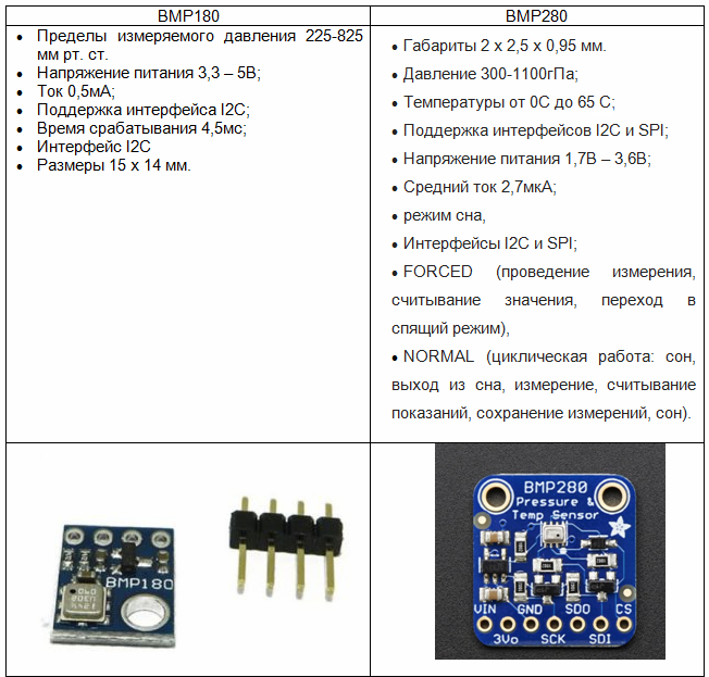
If the two previous instances were similar to each other, then BME280 sensor - This is a miniature weather station. 3 sensors are built in it:
-
Temperature;
-
Pressure;
-
Humidity.
Its technical characteristics:
-
Dimensions 2.5 x 2.5 x 0.93 mm;
-
Metal LGA-housing, equipped with 8 outputs;
-
Supply voltage 1.7 - 3.6V;
-
Availability of I2C and SPI interfaces;
-
Standby current consumption 0.1 µA.
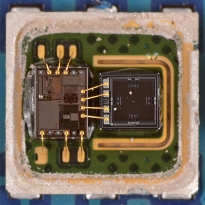
These examples are MEMS barometers. MEMS stands for microelectromechanical. This is a mechanical microstructure that uses capacitive phenomena and other principles for its work. Below you see an example of such a sensor in the context.
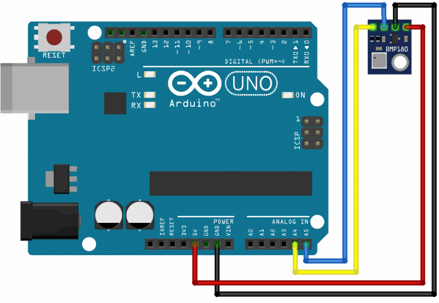
Connection diagram example:
And an example of program code:
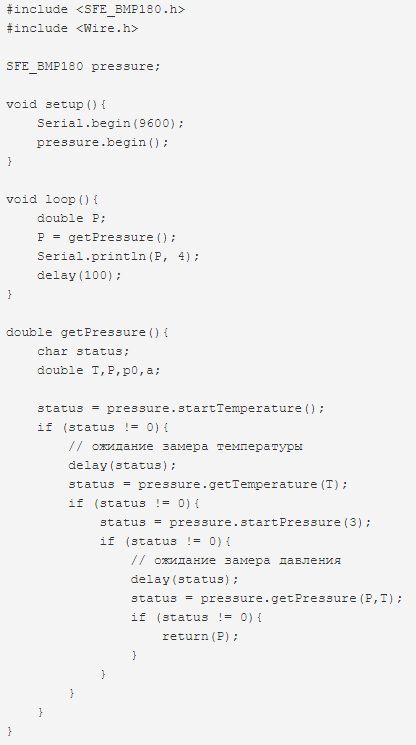
The logic of the program is simple:
1. Call subroutine (function) reading from the sensor.
2. Request for readings of the temperature sensor integrated in the barometer.
3. We are waiting for time to evaluate the temperature sensor;
4. Read the result of temperature measurements;
5. Request pressure values;
6. We are waiting for the pressure measurement time;
7. Read the pressure value;
8. Return the pressure value from the function.
An interesting fact is that there are four options for reading values, they are specified as an argument in the startPressure function, the second sign is from 0 to 3, where 0 is a rough estimate, and 3 is an exact estimate.
Motion Sensor
The most common motion sensor for Arduino is HC SR501 IR Sensor Module. A feature of this module is that it has an adjustment of the response distance and the delay time of the output signal after operation.
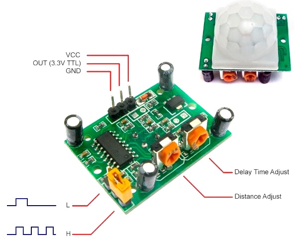
Module Features:
1. Supply voltage 4.5 - 20 V.
2. Quiescent current ≈ 50 μA;
3. Output signal voltage (logic level): 3.3 V;
4. Operating temperature range - from -15 ° C to 70 ° C;
5. Dimensions: 32 * 24 mm;
6. Field of view - 110 °;
7. Maximum operating distance - from 3 to 7 m (adjustable); Above 30 ° C, this distance may decrease.
Wiring diagram:
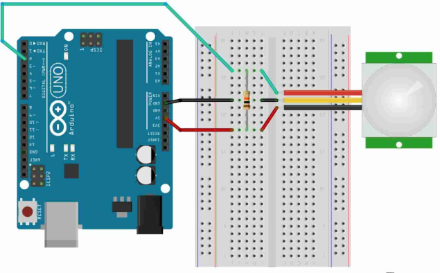
How to work with him we considered in an article published earlier: Schemes of motion sensors, the principle of their work and wiring diagrams
Water level sensor
Designed to indicate fluid level.
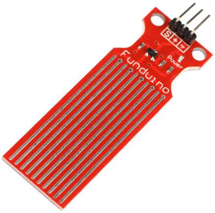
Specifications:
1. Supply voltage 3-5V
2. Consumption current> 20 mA
3. Analog
4. Dimensions of the measuring zone 40x16 mm
5. Permissible humidity 10% - 90%
Example code:
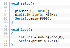
The output values are from 0 (in the dry state) to 685 (it may differ actually depends on the conductivity of the water). Do not forget about electrolysis, when measuring the level of salt or hard water, it will corrode.
Leakage sensor
The module consists of two parts - the sensor itself and the comparator, can be built on the LM393, LM293 or LM193.
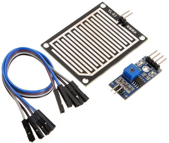
Thanks to the comparator, the analog signal is converted to digital.
Wiring diagram:
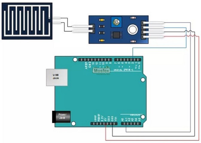
Board Pinout:
-
VCC - power, must match the power of the Apduino board, in most cases it is 5V;
-
GND - common wire;
-
AO - analog signal;
-
DO is a digital signal.
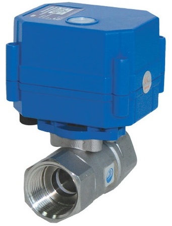
There is a tuning resistor on the comparator board, it sets the sensitivity of the sensor. It can act as a signal of rain or leaking something, and when paired with such a crane, it can work as protection against pipeline leaks in the apartment:
The video shows how it works:
Humidity sensor
Commonly used in automatic watering projects, to determine soil moisture, as well as the previous one consists of electrodes and a board with a comparator.
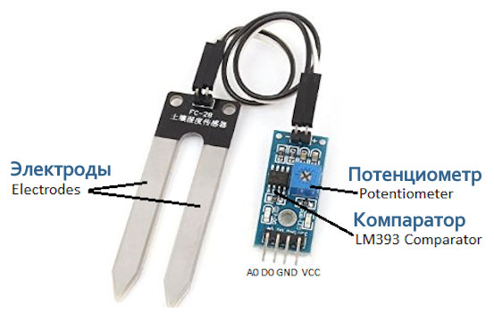
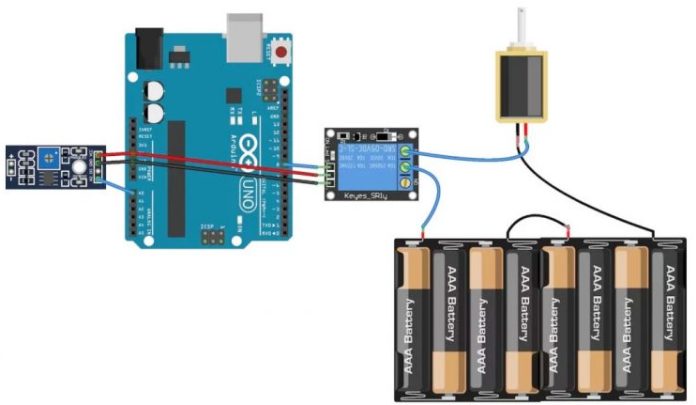
It can work both in analog and digital modes. An example of a connection diagram for an automatic irrigation system with a crane based on an engine:
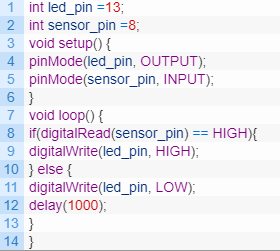
And an example of program code for processing a digital signal from a humidity sensor:
Conclusion
We examined popular sensors, but there are also many others. These are a variety of vibration sensors, gyroscopes, accelerometers, radiation sensors and more.
The aim of the article was to collect in one place a variety of elements that may be useful to a beginner electronics engineer for the implementation of their projects. If you are interested in a particular sensor - write in the comments and we will consider it in more detail.
For your convenience, we have compiled for you a table with an estimated cost and a list of popular sensors for Arduino, in the order in which they were considered in the article:Sensors for Arduino
Prices are taken from online stores in Russia or Ukraine. In China, they cost 2 or more times cheaper.
See also at i.electricianexp.com
:
