Categories: Featured Articles » Practical Electronics
Number of views: 31007
Comments on the article: 0
What is the difference between analog and digital sensors
 The term “sensor” itself means a mechanism designed to measure a parameter in order to further process the measurement result. The sensor circuit generates a signal in a convenient form for transmission, then the signal is converted, processed or stored. Without sensors in some modern areas of industry, and in many equipment of various kinds, just can not do.
Electronics today makes it possible to manufacture electronic sensors capable of monitoring processes by several parameters at once, which greatly expands the possibilities for constructing complex measuring and actuating devices.
The sensor necessarily contains in its design a sensitive element and often a converter part. The main characteristics of electronic sensors are their sensitivity and measurement error.
To date, analog and digital sensors are used everywhere for scientific and research purposes, in telemetry, in quality control systems and automated control, and in many other areas, which can be listed endlessly. One way or another, these are always those technical areas where it is necessary to obtain information about the measurement of a quantity.
The purpose of this article will be to give the reader an idea of the difference between analog and digital sensors. We will look at a simple example of how the same value can be monitored by an analog and digital sensor, and in which case it is advisable to use an analog sensor, and in which - digital.
An analog sensor generates an analog signal at the output, the level value of which is obtained as a function of time, and such a signal changes continuously, the signal constantly takes any of the many possible values.
So, analog sensors are suitable for tracking continuously changing physical greatness, for example thermocouple terminal voltage signals a temperature change, and the voltage on the secondary winding of the current transformer is in a certain period proportional to the current of the controlled circuit. The microphone is a sensor of pressure changes from a sound wave, etc.
Digital sensors, in turn, generate an output signal that can be recorded in the form of a sequence of numerical values, often the signal is binary, that is, either a high signal level or low (zero). When a digital sensor signal needs to be transmitted over an analog channel, such as radio, resort to the use of modulation.
Digital sensors dominate communication systems because their output signals are easily regenerated in the repeater, even if noise is present. And the analog signal, in this sense, will be distorted by noise, and the data will turn out to be inaccurate. When transmitting information, digital sensors are more acceptable.
Let's look at specific simple examples, first an analog sensor, then a digital one, and in our example these sensors will measure the same parameter - current.
Analog current sensor

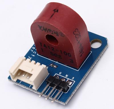
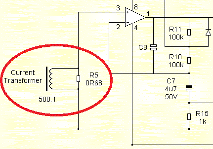
Analog current sensor on current transformer. Why analog? Because in this case, the current can increase, for example, from 0 to 5 amperes, while the voltage (signal) at the output will increase proportionally from 0 to 1 volt. Such a sensor allows continuous monitoring of the current in the measured circuit.
For example, being installed in PWM power supply, the analog current sensor will generate an analog feedback signal, and the higher its value, the greater the current flowing in the load circuit at the moment, and the control pulse width adjustment circuit, built on a comparator, will reduce the duration of the control pulse, leading the load current to the required nominal value, so that the output power does not increase unacceptably high.

Digital current sensor
Now let's say that we are dealing with a resonant electric power converter, where it is necessary to monitor current fluctuations in a resonant LC circuit, and an important parameter will be not only and not so much the magnitude of the current as its direction.
In this case, you can also use a current transformer, only the output of the current transformer will not be loaded on the resistor, but on the zener diode or on the limiting diodes. What will it give?
When the current flows in one direction, the voltage on the secondary side of the current transformer will have a certain high value, and when in the other direction - a certain low value. So it turns out “1” and “0” - a digital signal, and intermediate values are not needed, they are monitored by another circuit, analog.
Current direction sensors can also be implemented on the basis of the Hall effect (digital Hall sensors), but in our example the goal was to show the fundamental difference between the analog and digital sensors, so let us leave the Hall sensor aside.
See also at i.electricianexp.com
:

