Categories: How does it work
Number of views: 211000
Comments on the article: 8
What is a switching power supply and how does it differ from a conventional analog
In many electrical appliances, the principle of implementing secondary power has long been applied through the use of additional devices, which are entrusted with the function of providing electricity to circuits that need power from certain types of voltage, frequency, current ...
For this, additional elements are created: Power suppliestransforming the voltage of one type into another. They can be:
-
built into the consumer’s case, as on many microprocessor devices;
-
or made by separate modules with connecting wires, similar to a conventional charger on a mobile phone.
In modern electrical engineering, two principles of energy conversion for electric consumers, based on:
1. the use of analog transformer devices for transmitting power to the secondary circuit;
2. switching power supplies.
They have fundamental differences in their design, work on different technologies.
Transformer power supplies
Initially, only such designs were created. They change the voltage structure due to the operation of a power transformer powered from a 220 volt household network, in which the amplitude of the sinusoidal harmonic decreases, then sent to a rectifier device consisting of power diodes, which are usually connected according to the bridge circuit.
After that, the ripple voltage is smoothed in parallel by a capacitance selected according to the value of the allowable power, and is stabilized by a semiconductor circuit with power transistors.
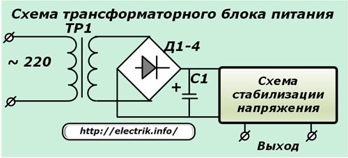
By changing the position of the tuning resistors in the stabilization circuit, it is possible to adjust the voltage at the output terminals.
Switching Power Supplies (UPS)
Such design developments appeared in large numbers several decades ago and began to enjoy increasing popularity in electrical devices due to:
-
the availability of completing a common elemental base;
-
reliability in execution;
-
the possibilities of expanding the working range of output voltages.
Almost all sources of switching power supply differ slightly in design and operate according to one scheme typical of other devices.
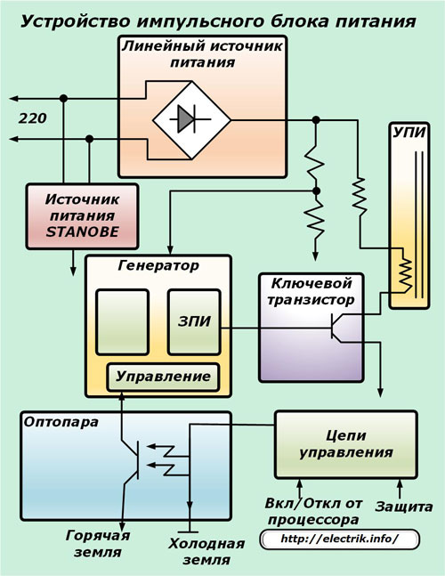
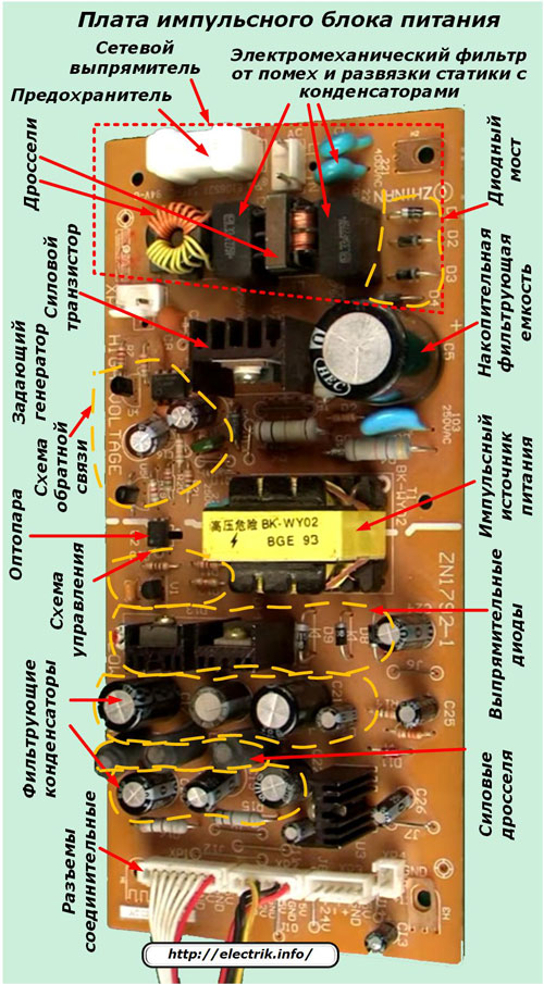
The main parts of power supplies include:
-
a network rectifier assembled from: input chokes, an electromechanical filter that provides detuning from interference and isolation of statics with capacitors, a mains fuse and a diode bridge;
-
cumulative filtering capacity;
-
key power transistor;
-
master oscillator;
-
feedback circuit made on transistors;
-
optocoupler;
-
switching power supply, from the secondary winding of which a voltage is emitted for conversion into a power circuit;
-
rectifier diodes of the output circuit;
-
control circuit output voltage, for example, 12 volts with tuning made on an optocoupler and transistors;
-
filter capacitors;
-
power chokes, performing the role of voltage correction and its diagnostics in the network;
-
output connectors.
An example of an electronic board of a similar switching power supply with a brief designation of the element base is shown in the picture.
How does a switching power supply
The switching power supply produces a stabilized supply voltage through the use of the principles of interaction of the elements of the inverter circuit.
The network voltage of 220 volts is supplied through the connected wires to the rectifier. Its amplitude is smoothed by a capacitive filter due to the use of capacitors withstanding peaks of the order of 300 volts, and is separated by an interference filter.
Input diode bridge rectifies the sinusoids passing through it, which are then transformed by a transistor circuit into high-frequency and rectangular pulses with a certain duty cycle. They can be converted:
1. with galvanic separation of the power supply network from the output circuits;
2. without performing such a denouement.
Isolated Switching Power Supply
In this case, high-frequency signals are sent to a pulse transformer, performing galvanic isolation of the circuits. Due to the increased frequency, the efficiency of using a transformer increases, the dimensions of its magnetic circuit and weight are reduced. Most often, ferromagnets are used for a material of such a core, and electrical steel is practically not used in these devices. It also helps minimize overall design.
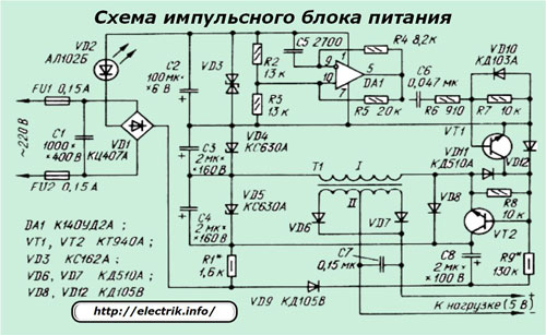
One of the versions of the switching power supply circuit with transformer isolation of the circuits is shown in the picture.
In such devices, there are three interconnected chains:
1. PWM controller;
2. a cascade of power keys;
3. pulse transformer.
How does a PWM controller work?
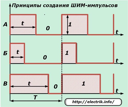
A controller is a device that controls a process. In the power supply unit under consideration, it is the process of converting pulse-width modulation. It is based on the principle of generating pulses of the same frequency, but with different switching times.
The momentum supply corresponds to the designation of a logical unit, and the absence corresponds to zero. Moreover, they are all equal in magnitude and frequency (have the same oscillation period T). The duration of the on state of the unit and its relation to the period change and allow you to control the operation of electronic circuits.
Typical changes in the SHIP sequences are shown in the graph.
Controllers usually create such pulses with a frequency of 30 ÷ 60 kHz.
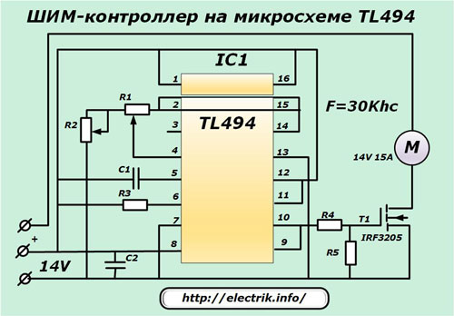
An example is a controller made on a TL494 chip. To adjust the frequency of generation of its pulses, a circuit consisting of resistors with capacitors is used.
Work cascade of power keys
It consists of powerful transistors that are selected from bipolar, field, or IGBT models. An individual control system can be created for them on other low-power transistors or integrated drivers.
Power keys can be turned on in various ways:
-
pavement;
-
half bridge;
-
with a midpoint.
Pulse transformer
The primary and secondary windings mounted around a magnetic core made of ferrite or alsifer can reliably transmit high-frequency pulses with frequencies up to 100 kHz.
Their work is complemented by chains of filters, stabilizers, diodes and other components.
Switching power supplies without galvanic isolation
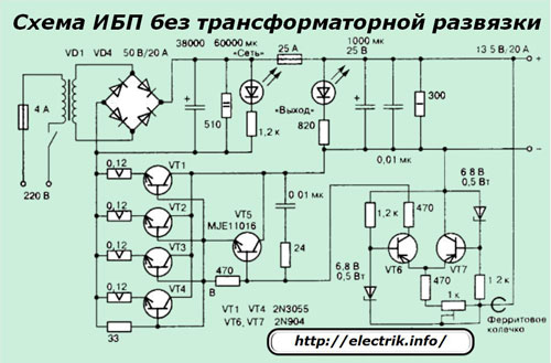
In switching power supplies designed according to algorithms that exclude galvanic isolation, a high-frequency isolation transformer is not used, and the signal goes directly to the low-pass filter. A similar principle of operation of the circuit is shown below.
Features of output voltage stabilization
All switching power supplies incorporate elements that provide negative feedback with the output parameters. Due to this, they have good stabilization of the output voltage under changing loads and fluctuations in the supply network.
The methods for implementing feedback depend on the scheme used to operate the power supply. It can be carried out in units operating with galvanic isolation due to:
1. intermediate effect of the output voltage on one of the windings of a high-frequency pulse transformer;
2. The use of an optocoupler.
In both cases, these signals control the duty cycle of the pulses supplied to the output of the PWM controller.
When using a circuit without galvanic isolation, feedback is usually created by connecting a resistive voltage divider.
Advantages of switching power supplies over conventional analog
When comparing the designs of blocks with equal performance indicators, switching power supplies have the following advantages:
1. reduced weight;
2. increased efficiency;
3. lower cost;
4. extended range of supply voltages;
5. the presence of built-in protections.
1. The reduced weight and dimensions of switching power supplies are explained by the transition from low-frequency energy conversions by powerful and heavy power transformers with control systems located on large cooling radiators and operating in a constant linear mode to pulse conversion and regulation technologies.
By increasing the frequency of the processed signal, the capacitance of the voltage filters and, accordingly, their dimensions are reduced. Their straightening scheme is also simplified up to the transition to the simplest one-half-wave.
2. For low-frequency transformers, a significant proportion of energy loss is created due to the release and dissipation of heat when performing electromagnetic transformations.
In impulse blocks, the greatest energy losses are created during the occurrence of transients during switching of power key cascades. And the rest of the time, transistors are in a stable position: open or closed. With this condition, all conditions are created for the minimum loss of electricity, when the efficiency can be 90 ÷ 98%.
3. The price of switching power supplies is gradually reduced due to the ongoing unification of the element base, which is made by a wide range of fully mechanized enterprises with robot machines. In addition, the operation mode of power elements based on controlled keys allows the use of less powerful semiconductor components.
4. Pulse technology allows you to power supply units from voltage sources with different frequencies and amplitudes. This expands the scope of their application in operating conditions with various standards of electrical energy.
5. Thanks to the use of small-sized digital-technology semiconductor modules, it is possible to reliably integrate protections into the design of pulse blocks, which control the occurrence of short-circuit currents, disconnect loads at the output of the device, and other emergency modes.
For conventional transformer power supplies, such protections were created on the old electromechanical, relay, semiconductor base. Applying digital technology to them in most schemes now does not make sense. The exception is food cases:
-
low-power control circuits of complex household appliances;
-
low-precision control devices of high accuracy, for example, used in measuring equipment or metrological purposes (digital electricity meters, voltmeters).
Disadvantages of switching power supplies
V / h interference
Since switching power supplies operate on the principle of converting high-frequency pulses, they in any design produce interference transmitted to the environment. This creates the need to suppress them in various ways.
In some cases, noise cancellation can be inefficient, which eliminates the use of switching power supplies for certain types of precision digital equipment.
Power limits
Switching power supplies have a contraindication to work not only at high, but also low loads. If a sharp decrease in the current outside the minimum critical value occurs in the output circuit, the start-up circuit may fail or the unit will issue a voltage with distorted technical characteristics that do not fit into the operating range.
And in this article, read about repair of switching power supplies.
See also at i.electricianexp.com
:

