Categories: Featured Articles » Practical Electronics
Number of views: 15996
Comments on the article: 3
Inductor to protect against common mode noise generated by a switching power supply
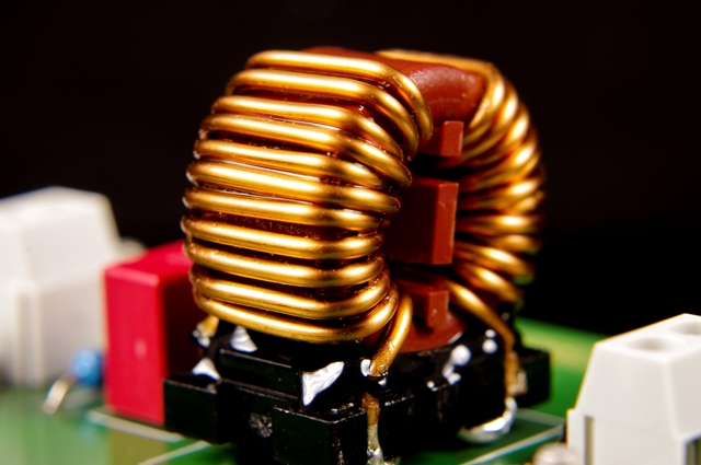
Common mode choke is the most important component of the input filter of any switching power supply. The fact is that during the operation of a pulse converter of any topology, when switching field-effect transistors, common-mode interference occurs, which propagate in the conductors and along the tracks of the printed circuit boards.
These interferences are harmful high-frequency impulse currents that flow simultaneously along the plus and minus wires, and in the same direction. If these interference finally gets into the AC power network, then they can not only lower the quality of functioning of the devices included in the network in the neighborhood, but even disable them, especially the signal circuits of digital units.

For this reason, today all household appliances, which in principle can become sources of common-mode interference, are equipped with common-mode chokes. Such devices include: printers, scanners, monitors, players, PC peripherals, PCs themselves, etc.
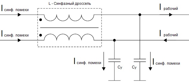
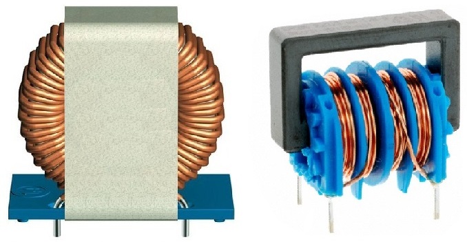
In each device where there is a switching power supply, a double-winding common-mode choke on an annular or U-shaped core is necessarily installed at the input after the filter capacitor. Capacitors are installed on the sides of the inductor to suppress differential interference (differential interference is a separate issue), as well as high-voltage Y-capacitors.
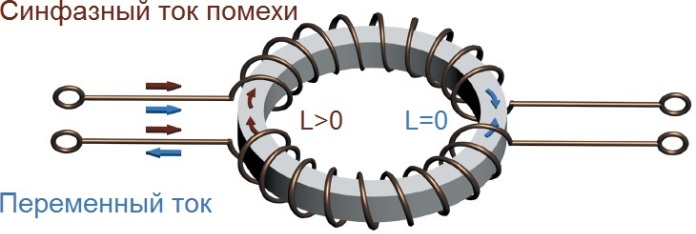
The two common-mode chokes are wound around a common core of high magnetic permeability material such as ferrite. And if in-phase noise currents flow from the wires from the source to the network, then the magnetic fields of these currents will add up, and the inductance of the inductor will fully manifest itself by suppressing these currents: the lion's share of their energy will be spent on creating a magnetic field, thus the interference amplitude It will significantly decrease, and if it comes to an alternating current network, if it comes, it will be greatly weakened, no longer able to manifest itself maliciously.

On the other hand, when alternating current from the network is supplied to the consumer, encountering an in-phase choke on its way, it does not experience absolutely any resistance, because the ohmic resistance of the wires is negligible, and the magnetic fields of the currents in the two conductors are directed opposite to each other and are equal in magnitude between by myself.
The coils are absolutely identical and wound perfectly symmetrically. Often these windings are made by winding in two wires, which minimizes the leakage inductance between them. It turns out that the common-mode inductor inductance for a conventional pulse current, which in two wires has the opposite direction and the same value, will be zero. Thus, the common-mode choke only interferes with common-mode interference, the source of which is the power supply, and not the AC mains.

And if there was no common-mode inductor, then the common-mode interference would freely penetrate into the alternating current network, as well as capacitors between the wires on the path of its propagation.
As for the effective capacitors on the common mode path, this is - ceramic high voltage capacitors (Y-capacitors) with a capacity of nanofarads installed between each power wire and the ground bus so that part of the common-mode noise energy goes into the ground. For the operating current, these capacitors represent a very large resistance, and therefore do not affect the efficiency of the device.

Commercially available output and SMD common mode chokes for switching power supply cards offer several advantages.They are quite compact, do not take up much space on the printed circuit board, their active resistance does not exceed units of mOhm, and the maximum allowable supply current through the inductor depends essentially only on the thickness of the wire and the power of the device. The rated current varies from 1 mA to 10 A. Typical inductances are from 10 μH to 100 mH.
See also at bgv.electricianexp.com
:
