Categories: Practical Electronics, All about LEDs
Number of views: 90682
Comments on the article: 0
Circuitry of power supplies for LED strips and not only
LEDs replace these types of light sources, such as fluorescent lamps and incandescent lamps. Almost every house already has LED lamps, they consume much less than two of their predecessors (up to 10 times less than incandescent lamps and 2 to 5 times less than CFLs or energy-saving fluorescent lamps). In situations where you need a long light source, or you need to organize illumination of a complex shape in progress LED Strip Light.
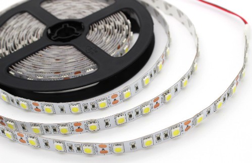
Led tape is ideal for a number of situations, its main advantage over individual LEDs and LED arrays are power sources. They are easier to find on sale in almost any electrical goods store, unlike drivers for high-power LEDs, moreover, the selection of a power supply is carried out only by power consumption, because the vast majority of LED strips have a supply voltage of 12 volts.
While for high-power LEDs and modules, when choosing a power source, it is necessary to look for a current source with the required power and rated current, i.e. consider 2 parameters, which complicates the selection.
This article discusses typical schemes of power supplies and their components, as well as tips for their repair for beginner hams and electricians.
Types and requirements for power supplies for LED strips and 12V LED lamps
The main requirement for a power source for both LEDs and LED strips is high-quality voltage / current stabilization, regardless of surges in the mains voltage, as well as low output ripples.
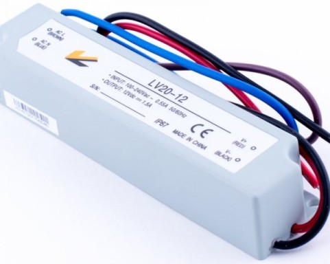
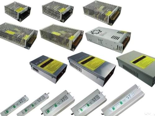
According to the type of execution, power supplies for LED products are distinguished:
-
Sealed. They are more difficult to repair, the case is not always amenable to accurate disassembly, and inside it can even be filled with sealant or compound.
-
Leakproof for indoor use. Better to repair, because the board is removed after unscrewing several screws.
By type of cooling:
-
Passive Aerial. The power supply is cooled by natural convection of air through the perforation of its housing. The disadvantage is the inability to achieve high power while maintaining overall dimensions;
-
Active air. The power supply is cooled using a cooler (a small fan, as installed on the PC system units). This type of cooling allows you to achieve more power at the same size with a passive power supply.
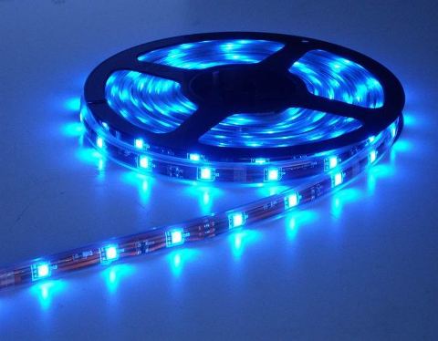
Power supply schemes for LED strips
It should be understood that there is no such thing in electronics as a “power supply for an LED strip”, in principle, any power supply with a suitable voltage and current greater than that consumed by the device will fit any device. This means that the information described below is applicable to almost any power supply.
However, in everyday life it is easier to talk about the power supply for its intended use for a particular device.
General structure of a switching power supply
For the last few decades, pulsed power supplies (UPS) are used to power LED strips and other equipment. They differ from transformer ones in that they work not at the frequency of the supply voltage (50 Hz), but at high frequencies (tens and hundreds of kilohertz).
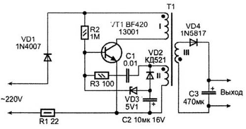
Therefore, for its operation, a high-frequency generator is needed, in cheap and designed for small currents (units of amperes) power supplies, a self-generating circuit is often found, it is used in:
-
electronic transformers;
-
electronic ballasts for fluorescent lamps;
-
mobile phone chargers;
-
cheap UPS for LED strips (10-20 W) and other devices.
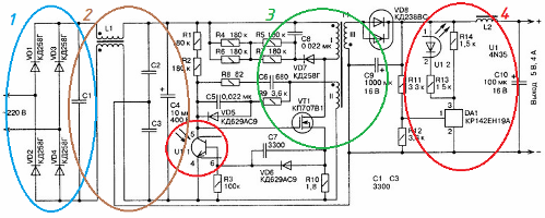
A diagram of such a power supply can be seen in the figure (click on the picture to enlarge):
Its structure is as follows:
1. Highlighted in blue diode bridgestanding at the input of the power supply unit, it rectifies the input alternating voltage, to supply the following nodes with a constant voltage of 220 * 1.41 = 310 V. In the event of a breakdown, check the presence and magnitude of the voltage BEFORE the bridge and AFTER it, if it is absent, you will need to replace the diodes or bridge if it is assembled in a hotel building.
It is not indicated in the diagram, but a fuse or low-resistance resistor may be present on the 220 V line, check its integrity before starting repairs.
2. A ripple filter is circled in brown, its main element is C4 - electrolytic capacitor. Its capacity depends on how much the manufacturer has saved, usually up to 220 microfarads per 400 volts. L1 - filter ripple and electromagnetic interference that occur during operation of a switching power supply. In most cheap power supplies, it is missing.
A common filter problem - drying, explosion or bloating of an electrolytic capacitor, leads to poor-quality operation of the entire switching power supply as a whole or its complete inoperability. You can replace it with the same and larger capacity, but suitable in size.
3. The power part VT1 power transistor is highlighted in green, in this case a field-effect transistor, but it can also be bipolar. T1 - pulse transformer with three windings: primary, secondary and basic.
The third winding is necessary for the generation of high-frequency oscillations - if the principle of the self-generating power supply unit is interesting, it is better to read the books of Moin, Zinoviev and other textbooks on pulse-type power supplies.
Pulse transformers are much smaller in size than network transformers, again due to work at high frequencies and are made not of iron, but of ferrite. Most often, the power switch fails.
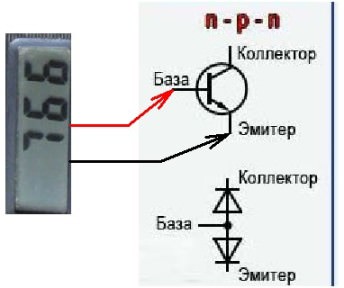
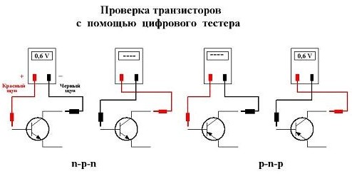
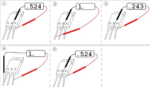
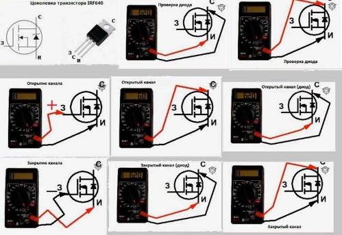
Ring the transistor multimeter in diode test mode, and you will immediately discover its breakdown or breakage. The remaining elements are the strapping of this node, individually rarely breaks down, mainly after the power transistor. However, you should always make sure that the nominal values of the resistors and capacitors are consistent.
The diodes in the strapping of the transformer VD7 and VD5 act as a snubber protecting the circuits from bursts of counter-EMF, at the moments of switching the transistor. They are also quite a busy and responsible node.
4. The voltage feedback loop is highlighted in red based on the adjustable zener diode TL431 and their analogues (any letters in the designation with numbers "431").Additional information about TL431:Legendary Analog Chips
The OS includes an optocoupler U1, with its help, an output signal is supplied to the power part of the oscillator and a stable output voltage is maintained.There may be no voltage in the output part due to the breakage of the VD8 diode, often this is a Schottky assembly, to be replaced. The bloated C10 electrolytic capacitor also often causes problems.
As you can see, everything works with a much smaller number of elements, the reliability is appropriate ...
More expensive and power supplies
The circuits that you will see below are often found in power supplies for LED strips, DVD players, radio tape recorders and other low-power devices (tens of watts).
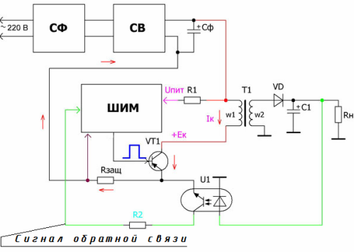
Before proceeding to the discussion of popular circuits, familiarize yourself with the structure of a switching power supply with a PWM controller.
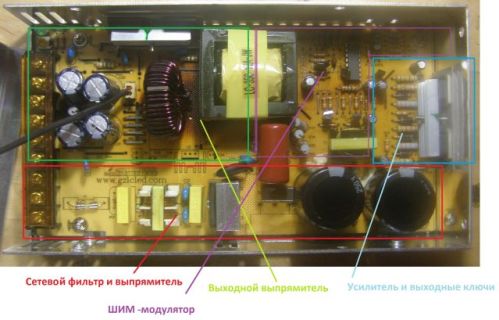
The upper part of the circuit is responsible for filtering, rectifying and smoothing the ripples of the mains voltage 220, essentially the same as in the previous type and in the subsequent ones.
The most interesting thing is the PWM block, the heart of any decent power supply. A PWM controller is a device that controls the duty cycle of the pulses of the output signal based on a setting defined by the user or feedback on current or voltage.PWM can control both the load power using a field (bipolar, IGBT) key, and a semiconductor controlled key as part of a converter with a transformer or inductor.
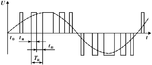
By changing the width of the pulses at a given frequency - you change the actual value of the voltage, while maintaining the amplitude, you can integrate it with C and LC circuits to eliminate ripple. This method is called Pulse Width Simulation, that is, signal modeling due to the width of the pulses (duty cycle / duty cycle) at a constant frequency.
In English, it sounds like a PWM-controller, or Pulse-Width Modulation controller.
The figure shows a bipolar PWM. Rectangular signals are the control signals on transistors from the controller, the dotted line shows the voltage form in the load of these keys - the effective voltage.
Better power supplies of low average power are often built on integrated PWM controllers with a built-in power switch. Advantages over the auto-generating scheme:
-
The operating frequency of the converter is independent of either the load or the supply voltage;
-
Better stabilization of output parameters;
-
The ability to more easily and reliably adjust the operating frequency at the design and modernization stage of the unit.
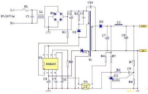
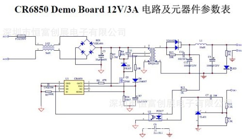
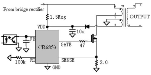
Below will be located a few typical schemes of power supplies (to enlarge, click on the picture):
Here, the RM6203 is both a controller and a key in one case.
This circuit uses external mosfet key.
The same thing, but on a different chip.
Feedback is carried out using a resistor, sometimes optocouplers connected to an input called Sense (sensor) or Feedback (feedback). Repair of such power supplies is generally similar. If all the elements are serviceable, and the supply voltage is supplied to the microcircuit (Vdd or Vcc leg), then the matter is most likely in it, more precisely can be determined using an oscilloscope looking at the output signals (drain, gate leg).
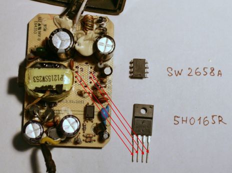
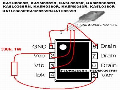
Almost always, you can replace such a controller with any analog with a similar structure, for this you need to compare the datasheet with the one that is installed on the board and the one that you have and solder it, observing the pinout, as shown in the following photos.
Or here is a diagram of the replacement of such microcircuits.
Powerful and expensive power supplies
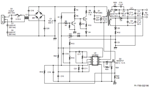
Power supplies for LED strips, as well as some power supplies for laptops are performed on the PWM controller UC3842.
The scheme is more complex and reliable. The main power component is Q2 transistor and transformer. During the repair, it is necessary to check the filtering electrolytic capacitors, the power switch, the Schottky diodes in the output circuits and the output LC filters, the supply voltage of the microcircuit, otherwise the diagnostic methods are similar.
However, a more detailed and accurate diagnosis is possible only with the use of an oscilloscope, otherwise - check the short circuits of the board, soldering of elements and breaks are more expensive. Replacing suspicious nodes with obviously working ones can help.
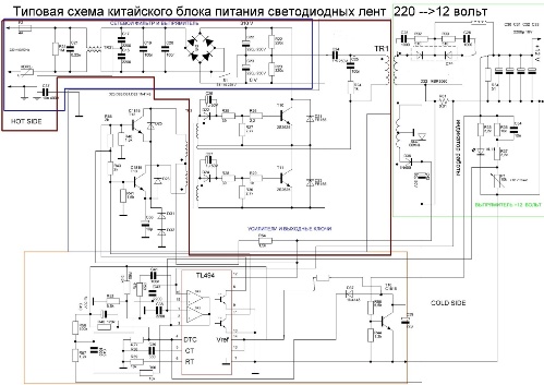
More advanced models of power supplies for LED strips are made on the almost legendary TL494 chip (any letters with the numbers "494") or its analogue KA7500. By the way, the majority of AT and ATX computer power supplies are built on these controllers.
Here is a typical power supply circuit on this PWM controller (click on the circuit):
Such power supplies are highly reliable and stable.
Brief verification algorithm:
1. We feed the microcircuit according to the pinout from an external power source of 12-15 volts (12 legs are plus, and minus 7 for 7 legs).
2. A voltage of 5 volts should appear on 14 legs, which will remain stable when the power changes, if it "floats" - a replacement chip.
3. On the 5th output there should be a sawtooth voltage to "see" it can only be done using an oscilloscope.If it is not there or the shape is distorted, we check that the nominal values of the RC timing circuit are connected to the 5 and 6 pins, if not, the diagram shows R39 and C35, they will be replaced, if nothing has changed after that, the microcircuit is out of order.
4. At the outputs 8 and 11 there should be rectangular pulses, but they may not be due to the specific feedback implementation scheme (conclusions 1-2 and 15-16). If you turn off and connect 220 V, for some time they will appear there and the unit will again go into defense - this is a sign of a working microcircuit.
5. You can check the PWM by shorting the 4 and 7 legs, the width of the pulses will increase, and shorting 4 by 14 legs - the pulses will disappear. If you get other results - the problem is in the MS.
This is the most concise test of this PWM controller. There is a whole book on “Switching power supplies for IBM PC” about repairing power supplies based on them..
Although it is dedicated to computer power supplies, but there is a lot of useful information for any radio amateur.
Conclusion
The circuitry of power supplies for LED strips is similar to any power supplies with similar characteristics, it can be easily repaired, modernized and adjusted to the required voltage, of course, within reasonable limits.
See also on our website:
Schematic diagrams of portable electronic devices power supplies
What is a switching power supply and how does it differ from a conventional analog
Tips for Repairing Switching Power Supplies
Video recording of the repair process of various household appliances
See also at bgv.electricianexp.com
:

