Categories: Practical Electronics, Repair of household appliances, How does it work
Number of views: 68101
Comments on the article: 3
Power supplies for electronic devices - device and principle of operation of the main circuits
Electronic devices can be divided into two groups: mobile and stationary. The first of them use the so-called primary power sources, - galvanic batteries or accumulators that have a supply of electricity.
It immediately recalls mobile phones, cameras, remote controls and many other portable devices. In this case, rechargeable batteries and batteries are beyond competition, since there is simply nothing to replace them with. The only inconvenience, the mobility fee is that the duration of such devices is limited by the battery capacity, and, as a rule, is small. An exception to this rule are, perhaps, watches. Their energy consumption is very low, which is incorporated at the design stage, so the clock can go on a single battery for a whole year, or even more.
Stationary devices, as a rule, receive food from secondary sources. Such sources of their own energy do not produce, but only convert the electric current to the required parameters: from a 220V mains voltage, the power supplies generate reduced voltages necessary to power semiconductor equipment. Such power supplies are often called networked.
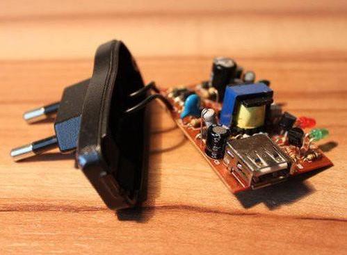
Hazardous Power Supplies
The simplest are power supplies with a quenching capacitor or resistor. Similar blocks were described in radio magazines in the nineties of the last century. The efficiency of such power supplies is extremely small no more than 20%, so they are used to power devices whose power is not more than a few watts: you can power one or two microcircuits.
The main disadvantage of such blocks is that they are not galvanically isolated from the primary network, as a result of which the entire circuit - the consumer is also under dangerous potential. Touching an element of such a circuit is completely undesirable, and even dangerous. Therefore, the establishment of such structures is performed using an isolation transformer described in the article “How to make a safety transformer”.
But even with such adjustment, these schemes still remain dangerous, therefore, they should not be recommended for use. If nevertheless such a scheme cannot be avoided (what's the point of making a separate source for power photo relaythat hangs high on a post?), one can only hope for the accuracy and literacy of the user.
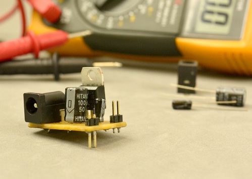
Safe blocks with blanking capacitor
The power supply circuit with a quenching capacitor and galvanic isolation from the network is described in the article "Thermostat for welding plastics" and shown in figure 1. The author of the scheme V. Kuznetsov.
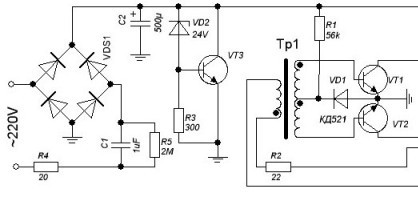
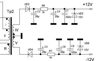
Figure 1. Power supply circuit with a blanking capacitor and galvanic isolation from the network
The scheme is described in detail in the mentioned article, was repeated many times (more than a dozen times) and showed excellent results. Therefore, here we note only the main points. The mains voltage through the quenching capacitor C1 is rectified by the bridge VD1 and stabilized at 24V by the stabilizer on the transistor VT3. A generator made on transistors VT1, VT2 is fed from this stabilizer. The “power” transformer Tr2 is made on a ferrite ring with a diameter of 20 mm.
Such a transformer at a frequency of 40 ... 50 KHz can give a load of up to 7 watts, which is enough to power the circuit described in the article. The output voltages are stabilized by the simplest parametric stabilizers on the Zener diodes VD5, VD6. Due to the presence of isolation transformer Tr2, the supplied load is galvanically isolated from the network, which ensures electrical safety of the circuit.
Imagine what it would look like thermocoupleunder network potential! But it should be noted that everything that is shown in the diagram to the right of the core of the transformer Tr2 is under the potential of the network, and requires careful and careful handling. Another diagram of a safe power supply with a quenching capacitor is shown in Figure 2.
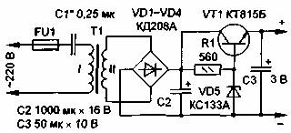
Figure 2. Diagram of a safe power supply with a quenching capacitor
The primary winding of the transformer of small-sized power supplies contains several (four ... seven) thousand turns of ultra-thin wire, - 0.05 ... 0.06 mm. In order not to wind such a winding, it is proposed to reduce the voltage on the primary winding to 30 ... 40V using a quenching capacitor. In this case, the primary winding contains no more than 600 ... 700 turns of a sufficiently thick wire (0.1 ... 0.15 mm). The secondary winding is calculated as usual for the required voltage.
The transformer can be wound on the Ш12 * 15 magnetic circuit from a subscriber loudspeaker. More precisely, the voltage value can be selected using the capacitor C1. Through the use of a transformer, the output of the power supply is galvanically isolated from the network. The power of such a power supply was enough to power a simple generator (six or seven chips of the K561 series) for setting up TVs. The supply voltage was 9 V. Details of the device and the establishment of this power supply can be found in the journal "Radio" No. 12_98.
Power supplies of modern equipment
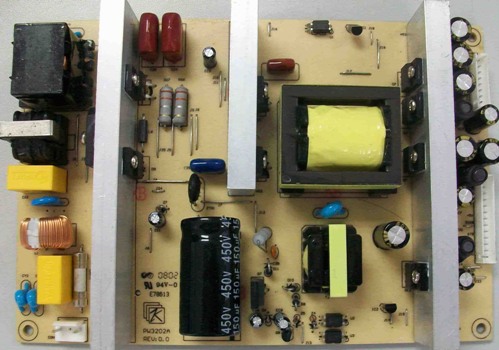
Modern industrial-made equipment, such as computers, music centers, televisions, for the most part has switching power supplies.
The main idea of such sources is as follows. The rectified network voltage is converted by an inverter into an alternating frequency of several tens, and sometimes hundreds of kilohertz. At such frequencies, transformers are obtained in very small sizes, which can significantly reduce the size and weight of the power supplies.
After the transformer, the pulse voltage is rectified and smoothed by filters, the size of which due to the high frequency is also small compared to traditional power supplies operating at the mains frequency. Output voltage stabilization is carried out in the primary circuit using pulse-width modulation - PWM, which also helps to increase efficiency and reduce the size of the power supply.
Not so long ago, it was believed that switching power supplies justify themselves only starting from a power of at least 100 watts. In this case, the specific power was considered the main criterion, i.e. power per 1 cubic decimeter of power supply volume. When the power of the pulsed source is below 100 W, the specific power of the pulsed source was lower than that of a conventional power supply. Simply put, the dimensions of a pulsed source could turn out to be larger than that of a conventional transformer.
But the technology does not stand still, the elemental base of electronics is developing very quickly. Modern industry has mastered the production of pulsed sources with a capacity of only a few watts, it’s enough to recall at least charging device for cell phones and “finger” batteries.
Here it’s just by sight that the specific power of such sources is higher than similar “chargers” (recently there were such) with a network transformer. This is how good things are in industrial production: huge savings are achieved on winding wire alone, transformer iron and miniature cases.
In the conditions of amateur technical creativity for the manufacture of a design in a single copy is quite suitable traditional power supply with mains transformer. Although occasionally you have to look for non-standard solutions to the power problem, for example, when repairing equipment.
Switching power supply from an electronic transformer
Here is a good practical example. In the imported sound mixer for some reason, the primary winding of the power transformer broke off, which was performed on an annular magnetic circuit.
The power of this transformer was about 20 watts, which led to sad thoughts that the number of turns of the primary winding is most likely not one thousand turns (the smaller the size of the transformer, the greater the number of turns per one volt, and the wire is thinner). And rewinding manually on the ring ... But this was not the main thing: the height of the ring transformer was so small that it did not seem possible to replace it with another, ready-made Sh-shaped one, the dimensions of the case did not allow it.
The use of an electronic transformer allowed to solve the problem, however, it took some refinement, which is described in the article "How to make a power supply from an electronic transformer?". The meaning of the alteration is that electronic transformer It is designed to work with incandescent lamps that are constantly connected to it, that is, the transformer starts up under load. If there is no load, then the circuit does not start. The same effect is observed with a slight load.
Imagine that the load is a powerful amplifier of sound frequency: as soon as the sound stopped, - pause, so the power supply turned off and did not start anymore. Here is the refinement of the electronic transformer and boils down to the fact that the power supply based on it turns on and works even without load.
An electronic transformer is just the case where the manufacture of a pulsed source is simplified to the limit: everything has already been done, the parts are all in place, the transformers are all wound up, and the price is just ridiculous. Just do it yourself kit! Even in the event of an unsuccessful experiment, throwing away will not be a pity. If you buy parts at retail, it will be much more expensive. Therefore, at home it is easier to make a conventional transformer power supply.
Network Adapters from China
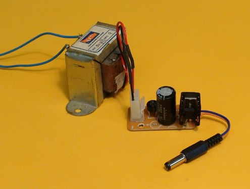
In the case when the load power is small, a Chinese-made network adapter may well save the situation. This is a well-known block made in the form of a large network plug with a tail ending in a connector, which is for some reason called a “jack”. Inside the plug there is a network transformer with a capacity of not more than 5 ... 7 watts, a rectifier bridge and a smoothing capacitor.
In some blocks there is a slide switch that allows you to stepwise change the output voltage within 5 ... 15V. The output voltage indicated on the switch corresponds to operation under load. For example, if 12V is indicated, then almost 18V can be used without load. Just the capacitor charges to the amplitude value. But under load, all the same, there will be 12V, which corresponds to the value of the effective value of the alternating voltage.

The design of such adapters is simplified to the limit: the Chinese did not even bother to install a fuse. By and large, it’s not too much here. The primary winding is wound with such a thin wire that it in itself is a good fuse. If the primary winding burns out, then it remains to throw this adapter and buy a new one.
The price of such adapters is low to repair them. The winding savings in these adapters are very noticeable. Such power supplies are noticeably heated even at idle, without load.
The next article will explain how you can independently make a simple and reliable power supply for your home laboratory.
Boris Aladyshkin
Continuation of the article: Home Lab Power Supplies
See also at bgv.electricianexp.com
:
