Categories: Featured Articles » Practical Electronics
Number of views: 219,937
Comments on the article: 5
Tips for Repairing Switching Power Supplies
A little about the use and design of the UPS
An article has already been published on the site "What is a switching power supply and how does it differ from a conventional analog"which describes the UPS device. This topic can be supplemented with a little story about the repair. The abbreviation UPS is often referred to. uninterruptable power source. In order to avoid discrepancies, we agree that in this article it is a Switching Power Supply.
Almost all switching power supplies used in electronic equipment are built according to two functional schemes.
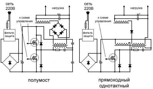
Fig. 1. Functional diagrams of switching power supplies
According to the half-bridge scheme, as a rule, fairly powerful power supplies, for example computer ones, are carried out. According to the two-stroke scheme, power supplies for high-power UMZCH pop-up artists and welding machines are also manufactured.
Anyone who has ever repaired amplifiers with a capacity of 400 or more watts knows perfectly well what weight they have. This is, of course, UMZCH with a traditional transformer power supply. UPS TVs, monitors, DVD-players are most often made according to the scheme with a single-stage output stage.
Although there are actually other types of output stages, which are shown in Figure 2.
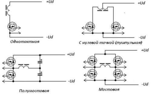
Fig. 2. Output stages of switching power supplies
Only power switches and the primary winding of the power transformer are shown here.
If you look closely at Figure 1, it is easy to see that the entire circuit can be divided into two parts - primary and secondary. The primary part contains a surge protector, a mains voltage rectifier, power switches and a power transformer. This part is galvanically connected to the AC network.
In addition to the power transformer, pulsed power supplies also use decoupling transformers, through which the control pulses of the PWM controller are fed to the gates (bases) of the power transistors. This way provides galvanic isolation from the network of secondary circuits. In more modern schemes, this isolation is carried out using optocouplers.
Secondary circuits are galvanically disconnected from the network using a power transformer: voltage from the secondary windings is supplied to the rectifier, and then to the load. Secondary circuits also supply voltage stabilization and protection circuits.
Very simple switching power supplies
They are performed on the basis of the oscillator when the master PWM controller is absent. An example of such a UPS is the Taschibra electronic transformer circuit.
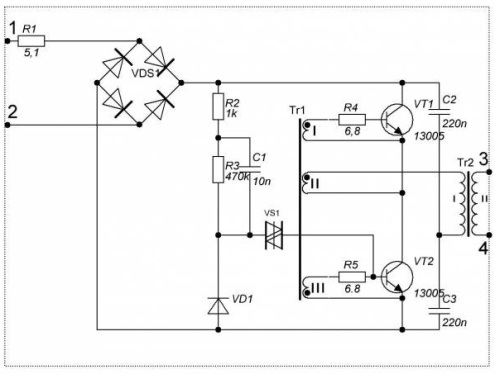
Fig. 3. Taschibra Electronic Transformer
Similar electronic transformers are produced by other companies. Their main purpose is halogen lamp power. A distinctive feature of such a scheme is simplicity and a small number of parts. The disadvantage is that without load this circuit simply does not start, the output voltage is unstable and has a high ripple level. But the lights still shine! In this case, the secondary circuit is completely disconnected from the mains.
It is obvious that the repair of such a power supply is reduced to the replacement of transistors, resistors R4, R5, sometimes diode bridge VDS1 and resistor R1, acting as a fuse. There is simply nothing more to burn in this scheme. At a low price for electronic transformers, they often just buy a new one, and repair is done, as they say, “out of love for art”.
Safety first
As soon as there is such a very unpleasant neighborhood of the primary and secondary circuits that during the repair process you must, even if by accident, have to touch it with your hands, you should recall some safety precautions.
You can touch the switched on source with only one hand, in no case with both at once.This is known to everyone who works with electrical installations. But it is better not to touch at all, or, only after disconnecting from the network by pulling the plug from the outlet. Also, you should not solder anything on the switched on source or simply twist it with a screwdriver.
In order to ensure electrical safety on the power supply boards, the “dangerous” primary side of the board is surrounded by a fairly wide strip or shaded with thin strips of paint, usually white. This is a warning that it is dangerous to touch this part of the board.
Even a switched-off switching power supply can be touched by hands only after a while, at least 2 ... 3 minutes after switching off: the charge remains on high-voltage capacitors for a long time, although discharge resistors are installed in parallel with capacitors in any normal power supply. Remember how the school offered each other a charged capacitor! Killing, of course, will not kill, but the blow is quite sensitive.
But the worst thing is not even that: well, think of it, I tweaked a little. If you immediately ring the electrolytic capacitor with a multimeter, then it’s quite possible to go to the store for a new one.
When such a measurement is expected, the capacitor must be discharged, at least with tweezers. But it is better to do this using a resistor with a resistance of several tens of kOhm. Otherwise, the discharge is accompanied by a bunch of sparks and a fairly loud click, and for a capacitor such a short circuit is not very useful.
And yet, when repairing, you have to touch the switched-on switching power supply, at least for some measurements. In this case, an isolation transformer will help to protect your loved one from electric shock as much as possible, often called a safety transformer. How to make it, you can read in the article “How to make a safety transformer”.
If in a nutshell, then this is a transformer with two windings for 220V, power 100 ... 200W (depends on the power of the UPS being repaired), the electrical circuit is shown in Figure 4.
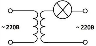
Fig. 4. Safety transformer
The left winding according to the scheme is connected to the network, to the right winding through a light bulb, a faulty switching power supply is connected. The most important thing with this inclusion is that with one hand you can touch any end of the secondary winding without fear, as well as with all the elements of the primary circuit of the power supply.
On the role of the bulb and its power
Most often, the repair of a switching power supply unit is carried out without an isolation transformer, but as an additional safety measure, the unit is switched on through a light bulb with a power of 60 ... 150W. The behavior of the light bulb can, in general, judge the status of the power supply. Of course, such an inclusion will not provide galvanic isolation from the network, it is not recommended to touch it with your hands, but it can completely protect it from smoke and explosions.
If, when connected to the mains, the bulb lights up in full heat, then you should look for a malfunction in the primary circuit. As a rule, this is a punctured power transistor or rectifier bridge. During normal operation of the power supply, the light first flashes quite brightly (capacitor charge), and then the filament continues to glow dimly.
There are several opinions about this light bulb. Someone says that it does not help get rid of unforeseen situations, and someone believes that the risk of burning a newly sealed transistor is much reduced. We will adhere to this point of view, and use the repair bulb.
About collapsible and non-collapsible cases
Most often, switching power supplies are performed in enclosures. It is enough to recall computer power supplies, various adapters included in the outlet, chargers for laptops, mobile phones, etc.
In the case of computer power supplies, everything is quite simple. Several screws are unscrewed from the metal case, the metal cover is removed and, please, the entire board with the details is already in hand.
If the case is plastic, then you should look at the back side, where the power plug is located, small screws. Then everything is simple and clear, he turned away and removed the cover. In this case, we can say that it was just lucky.
But recently, everything has been moving towards simplifying and reducing the cost of structures, and the halves of the plastic case simply stick together, and quite firmly. One comrade told how he transported a similar block to some workshop. When asked how to disassemble it, the masters said: “Are you not Russian?” Then they took a hammer and quickly split the case into two halves.
In fact, this is the only way to disassemble plastic glued cases. It’s only necessary to pound accurately and not very fanatically: under the influence of blows on the body, tracks leading to massive parts, for example, transformers or chokes, can break off.
A knife inserted into the seam also helps, and lightly tapping on it with the same hammer. True, after assembly there are traces of this intervention. But let there be minor traces on the case, but you don’t have to buy a new block.
How to find a circuit
If in the old days almost all domestic devices were supplied with circuit diagrams, modern foreign electronics manufacturers do not want to share their secrets. All electronic equipment is completed only with a user manual, which shows which buttons to press. Schematic diagrams are not attached to the user manual.
It is assumed that the device will work forever or repairs will be carried out in authorized service centers, where there are repair manuals called service manuals. Service centers do not have the right to share this documentation with everyone who wants it, but praise the Internet, these service manuals can be found on many devices. Sometimes this can happen for free, that is, for nothing, and sometimes the necessary information can be obtained for a small amount.
But even if the desired circuit could not be found, you should not despair, especially when repairing power supplies. Almost everything becomes clear upon careful consideration of the board. This powerful transistor is nothing more than an output key, but this chip is a PWM controller.
In some controllers, a powerful output transistor is “hidden” inside the chip. If these parts are sufficiently large, then they have a full marking, according to which you can find the technical documentation (data sheet) of the microcircuit, transistor, diode or zener diode. It is these details that form the basis of switching power supplies.
Datashits contain very useful information. If this is a PWM controller chip, then you can determine where are which conclusions, which signals are coming to them. Here you can find the internal device of the controller and a typical switching circuit, which helps a lot to deal with a specific circuit.
It is somewhat more difficult to find datasheets for small-sized SMD components. Full marking on a small case does not fit; instead, a code designation of several (three, four) letters and numbers is placed on the case. Using this code, using tables or special programs obtained again on the Internet, it is possible, though not always, to find reference data for an unknown element.
Measuring instruments and tools
To repair switching power supplies, you will need the tool that every radio amateur should have. First of all, these are several screwdrivers, side cutting pliers, tweezers, sometimes pliers and even the hammer mentioned above. This is for metalwork.
For soldering work, of course, you need a soldering iron, preferably several, of various capacities and dimensions. An ordinary soldering iron with a power of 25 ... 40W is quite suitable, but it is better if it is a modern soldering iron with a temperature regulator and temperature stabilization.
To solder multi-pin parts, it’s good to have at hand if not super expensive soldering station, then at least a simple inexpensive soldering hair dryer.This will allow soldering multi-pin parts without much effort and destruction of printed circuit boards.
To measure voltages, resistances and somewhat less often currents, you will need a digital multimeter, even if not very expensive, or a good old pointer tester. The fact that it is too early to write off the pointer device, what additional features it does not have in modern digital multimeters can be read in the article “Arrow and digital multimeters - advantages and disadvantages”.
Invaluable assistance in the repair of switching power supplies can provide oscilloscope. Here, it is also quite possible to use an old, even not very broadband, electron-beam oscilloscope. If of course there is the opportunity to purchase a modern digital oscilloscope, then this is even better. But, as practice shows, when repairing switching power supplies, you can do without an oscilloscope.
In fact, during the repair, two outcomes are possible: either repair, or make it even worse. Here it is appropriate to recall Horner's law: "Experience grows in direct proportion to the number of equipment that has been disabled." And although this law contains a fair amount of humor, this is exactly the case in the practice of repair. Especially at the beginning of the journey.
troubleshooting
Switching power supplies fail more often than other electronic components. First of all, the fact is that there is a high mains voltage, which after rectification and filtering becomes even higher. Therefore, the power switches and the entire inverter cascade operate in a very difficult mode, both electric and thermal. Most often, faults lie in the primary circuit.
Faults can be divided into two types. In the first case, the failure of the switching power supply is accompanied by smoke, explosions, destruction and carbonization of parts, sometimes tracks of the printed circuit board.
It would seem that the option is simple, just change the burned parts, restore the tracks, and it all works. But when you try to determine the type of microcircuit or transistor, it turns out that along with the case the marking of the part has also disappeared. What happened here, without a scheme, which is often not at hand, is impossible to find out. Sometimes repairs at this stage also end.
The second type of malfunction is quiet, as Lelik said, without noise and dust. The output voltages simply disappeared without a trace. If this switching power supply is a simple network adapter such as a charger for a cell or laptop, then first of all you should check the health of the output cord.
Most often, a break occurs either near the output connector or at the exit of the housing. If the unit is connected to the network using a cord with a plug, then first of all, make sure that it is working.
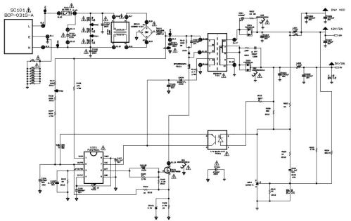
After checking these simplest chains, you can already climb into the wilds. As these wilds, we take the power supply circuit of the 19-inch monitor LG_flatron_L1919s. Actually, the malfunction was quite simple: it turned on yesterday, and today it does not turn on.
Despite the apparent seriousness of the device - after all, a monitor, the power supply circuit is quite simple and intuitive.

Description of the scheme and repair recommendations
After opening the monitor, several bloated electrolytic capacitors (C202, C206, C207) were detected at the output of the power supply. In this case, it is better to change all the capacitors at once, only six pieces. The cost of these parts is cheap, so you should not wait when they will also swell. After such a replacement, the monitor worked. By the way, such a malfunction in LG monitors is quite common.
Expanded capacitors triggered a protection circuit, the operation of which will be discussed later. If the power supply does not work after replacing the capacitors, you will have to look for other reasons. To do this, consider the scheme in more detail.
Fig. 5. Power supply of the monitor LG_flatron_L1919s (click on the picture to enlarge)
Line filter and rectifier
Mains voltage through input connector SC101, fuse F101, filter LF101 is fed to rectifier bridge BD101.The rectified voltage through the thermistor TH101 is supplied to the smoothing capacitor C101. This capacitor produces a constant voltage of 310V, which is supplied to the inverter.
If this voltage is absent or much less than the specified value, then check the mains fuse F101, filter LF101, rectifier bridge BD101, capacitor C101, and thermistor TH101. All of these parts are easy to check with a multimeter. If there is a suspicion of a C101 capacitor, then it is better to change it to a knownly good one.
By the way, the mains fuse just does not burn. In most cases, replacing it does not restore normal operation of the switching power supply. Therefore, you should look for other causes that lead to a blown fuse.
The fuse should be set to the same current as indicated on the diagram, and in no case should the “fuse” of the fuse. This can lead to even more serious malfunctions.
Inverter
The inverter is made in a single-cycle circuit. As a master oscillator, a PWM controller chip U101 is used to the output of which a power transistor Q101 is connected. The primary winding of transformer T101 is connected to the drain of this transistor through an inductor FB101 (pins 3-5).
An additional winding 1-2 with a rectifier R111, D102, C103 is used to power the PWM controller U101 in the steady-state mode of operation of the power supply. Starting the PWM controller when turned on is performed by the resistor R108.
Output voltage
The power supply produces two voltages: 12V / 2A to power the inverter of the backlight and 5V / 2A to power the logical part of the monitor.
From the winding 10-7 of the transformer T101 through the diode assembly D202 and the filter C204, L202, C205, a voltage of 5V / 2A is obtained.
In series with winding 10-7, winding 8-6 is connected, from which, using a diode assembly D201 and a filter C203, L201, C202, C206, C207, a constant voltage of 12V / 2A is obtained.
Overload protection
The source of the transistor Q101 includes a resistor R109. This is a current sensor, which is connected through the resistor R104 to pin 2 of the U101 chip.
With overload at the output, the current through the transistor Q101 increases, which leads to a voltage drop across the resistor R109, which is fed through the resistor R104 to the 2CS / FB pin of the U101 chip and the controller stops generating control pulses (pin 6OUT). Therefore, the voltage at the output of the power supply disappears.
It was this protection that was triggered by the expanded electrolytic capacitors, which were mentioned above.
Protection operation level 0.9V. This level is set by the source of exemplary voltage inside the microcircuit. Parallel to resistor R109, a ZD101 zener diode with a stabilization voltage of 3.3V is connected, which protects the 2CS / FB input from high voltage.
To the output 2CS / FB through the divider R117, R118, R107, a voltage of 310 V is supplied from the capacitor C101, which ensures the operation of the protection against high voltage. The permissible voltage range at which the monitor normally works is in the range of 90 ... 240V.
Output voltage stabilization
It is made on an adjustable zener diode U201 type A431. The output voltage 12V / 2A through the divider R204, R206 (both resistors with a tolerance of 1%) is supplied to the control input R of the zener diode U201. As soon as the output voltage becomes 12V, the zener diode opens and the LED of the PC201 optocoupler is lit.
As a result, the optocoupler transistor is opened, (pins 4, 3) and the power supply voltage of the controller through the resistor R102 is supplied to pin 2CS / FB. The pulses at pin 6OUT disappear, and the voltage at the 12V / 2A output starts to drop.
The voltage at the control input R of the zener diode U201 drops below the reference voltage (2.5 V), the zener diode locks and turns off the PC201 optocoupler. Pulses appear at the 6OUT output, the voltage of 12V / 2A starts to increase, and the stabilization cycle is repeated again. In a similar way, the stabilization circuit is built in many switching power supplies, for example, in computer ones.
Thus, it turns out that three signals are immediately connected to the input 2CS / FB of the controller using a wired OR: protection against overloads, protection against overvoltage of the network and the output of the output voltage stabilizer circuit.
Here it’s just right to recall how you can check the operation of this stabilization loop. Enough for this when OFF !!! from the network to the power supply unit, apply voltage to the 12V / 2A output from the regulated power supply unit.
It is better to catch on the output of the PC201 optocoupler with a pointer tester in the resistance measurement mode. As long as the voltage at the output of the regulated source is lower than 12V, the resistance at the output of the optocoupler will be large.
Now we will increase the voltage. As soon as the voltage becomes more than 12V, the arrow of the device will drop sharply in the direction of decreasing resistance. This suggests that the Zener diode U201 and the optocoupler PC201 are operational. Therefore, the stabilization of the output voltage should work fine.
In exactly the same way, you can check the operation of the stabilization loop in computer switching power supplies. The main thing is to figure out what voltage the zener diode is connected to.
If all these checks have been successful, and the power supply does not start, then you should check the Q101 transistor by dropping it from the board. With a working transistor, the U101 chip or its bundle is most likely to blame. First of all, this is an electrolytic capacitor C105, which is best checked by replacing a known-good one.
Boris Aladyshkin
See also at bgv.electricianexp.com
:

