Categories: Featured Articles » Practical Electronics
Number of views: 38124
Comments on the article: 1
How to check the diode bridge
A diode bridge or, as it is also called, a rectifier is needed for converting AC to DC. It is used wherever you need to get constant voltage power, regardless of the power of the device, current consumption or voltage.
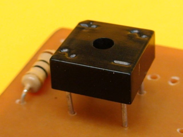
Device
For rectification of a single-phase voltage, a Gretz scheme of four is used diodes. If there is a transformer in the circuit with a tap from the midpoint, use a circuit of two diodes.
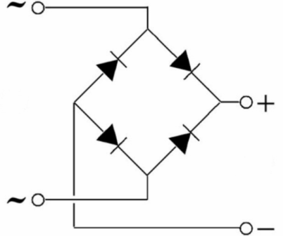
The bridge is called the inclusion of four diodes.
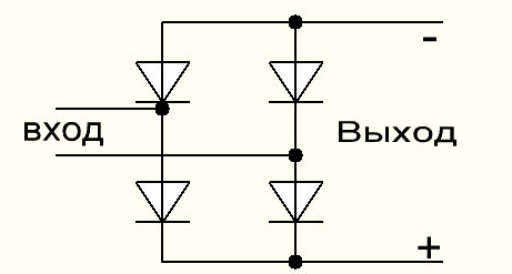
The diode bridge can be made in one housing, or it can be made of discrete diodes, that is, separate ones. The diode bridge input is called the AC voltage connection points, and the output is the point from which the constant is removed.
Alternating voltage is applied to the points at which the anode is connected to the cathode of the diodes. At the output, plus and minus are obtained, while the positive pole is removed from the connection point of the cathodes, i.e. plus power, and the connection point of the anodes is a minus.
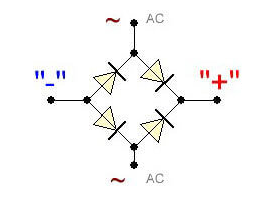
The figure shows a diagram of the diode bridge, where the AC connection points are indicated by "AC ~", and the constant output is "+" and "-".
Some beginners naively assume, based on the principle of reversibility of electric machines, that by applying a constant to the bridge on the remaining contacts, they will get a break. This is not so, it is not an electric machine and a converter is needed here.
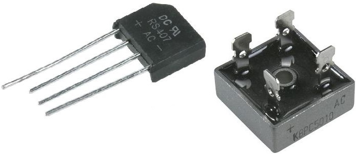
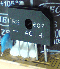
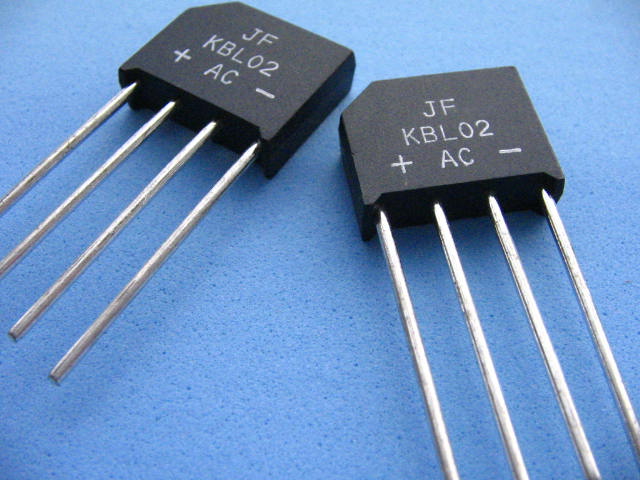
On modern diode bridges, the contacts are also marked: the input is AC or ~, and the parking outputs are + and -. Let's combine the scheme with the image of a real bridge to figure out how it looks in practice.
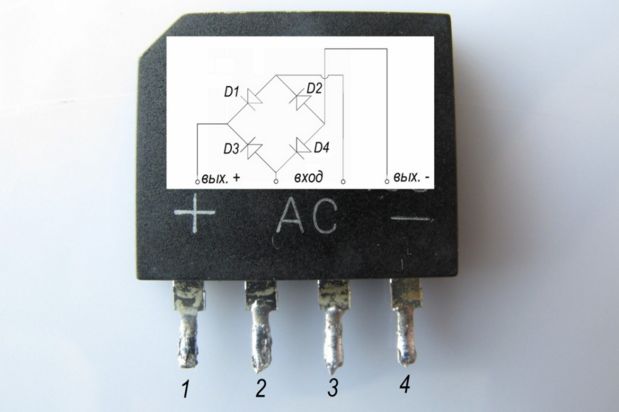
Where to install
A diode bridge is usually installed at the input of the power circuit, if the mains voltage of 220V is rectified, this solution is applied in switching power supplies, including a computer power supply, the device of which was considered in one of the previously posted on the site (see - How is a computer power supply) Or in the secondary winding of the transformer, this inclusion is used in conventional power supplies, such as a low-power radio for a home or an old TV.
In modern power supplies, pulsed circuits are often used, in which the diode bridge rectifies the mains voltage, and the transformer is controlled semiconductor switches (transistors).
Be careful:
If the diode bridge is at the input along the 220V line, then at its output a pulsating or smoothed (if there is a filtering capacitor) constant voltage sign with an amplitude of 310V. In any case, the rectified voltage increases, relative to the alternating one.
The same applies to the residual charge of filtering electrolytic capacitors, they can be shocked even when power is not supplied to the power supply board. They must first be discharged with an incandescent lamp or resistor.
You should not discharge the capacitance by shorting it with an iron tool: you may be shocked, you may damage the capacitors or the board tracks.
Let's start checking the diode bridge
I will reason with an example of a typical situation. There is an inoperative device and needs to be repaired.
You decided to repair the device, when disassembling, you saw a blown fuse on the board, a protective resistor, or a track on the printed circuit board.
After replacing the burned-out element and restoring the track, do not rush to turn it on. Beginning electronics engineers like to make "bugs" instead of a fuse, then, moreover, you can not turn on the board.
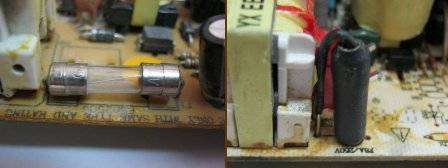
If the fuse failed for a reason, but due to problems on the power supply board, you will get the fuse to blow again.And if a bug was put in his place, then this inclusion should be accompanied by spectacular fireworks, possible damage to a wire or socket, broken plugs and automatic machines.
If a diode bridge is broken, then after a fuse there will be a short circuit on the board. To check the diode bridge for a breakdown without a multimeter, use the proven method: connect questionable pyatnia blocks, through an incandescent lamp for 40-100 W 220V. It will act as a current limiter and the board will not be damaged, and the fuse will not blow. The lamp is connected to the gap of one of the 220V power cables.
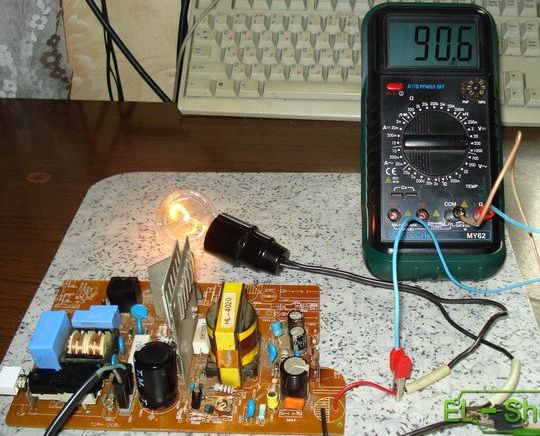
If the diode bridge is broken, the lamp will light up in full heat.
This is a fairly rough way to diagnose a diode bridge without a multimeter. The lamp can also light up with a working bridge, if the short circuit is in the circuit after it. You can check the diode bridge for an open without a multimeter and with indicator screwdriver, at its output, as already mentioned, there should be a high voltage, if it is installed on the 220V line, the neon indicator in the screwdriver should light up.
Checking the diode bridge with a multimeter
Any detail in the electrical circuit must be soldered before checking and ringing. You can, of course, check on the board, but it is likely to get false measurement results.
Also, if you ring the bridge from the side of the tracks and pads on the board, there is a chance of a lack of electrical contact with visually normal soldering. At the same time, if the diode bridge is assembled on a board from separate diodes, it is often convenient to check it without evaporating from the boards on its front side. In this case, you get convenient access to the metal legs of the diode.
You will need any digital multimeter, for example, the cheapest and most common type dt-830. Turn on the diode dialing mode, you can find it by the icon with its symbol.
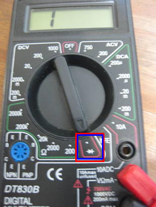
Often this mode is combined with the sound dialing mode. Any continuity and most ohmmeters consists of a pair of probes, one of which is a plus, and the second a minus. On a multimeter, most often a red probe is taken as a plus, and black for a minus.
As you know - the diode conducts current in one direction. In this case, the current flow is possible only when a positive probe (plus) is connected to the anode, and negative to the cathode. Then, when checking with a multimeter in this mode, the power silicon diode, the display shows numbers in the range 500 ... 700.
This is the number of millivolts that drops at the pn junction. If you saw these values - the diode is already half operational. If the numbers are large or a unit appears on the left side of the screen and nothing else - the diode is open. If the sound of the buzzer sounds or the screen is about 0, the diode is broken.
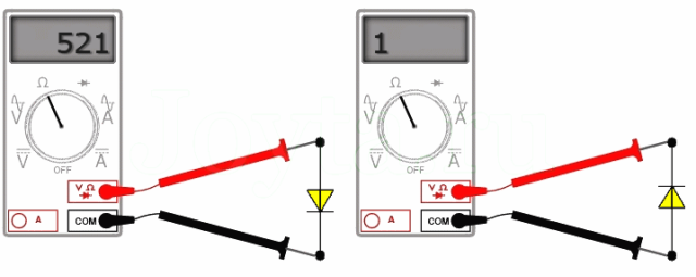
Now we need to determine if the current flows in the opposite direction. To do this, we change the probes in places, on the screen either there should be a value much greater than 1000, of the order of 1500, or a unit at the left side of the screen - this means a large value that goes beyond the measurement range. If the values are small - the diode is faulty, it is broken.
If both measurements coincided with those described, everything is in order with the diode.
In this way, a diode bridge of individual diodes is checked.
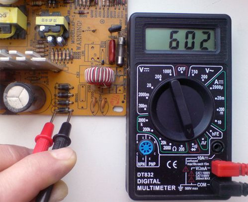
For Schottky diodes, the voltage drop from 0.3V, that is, when checking on the multimeter screen, a figure of the order of 300-500 will be displayed.
If you swap the probes in places - red to the cathode, and black to the anode, the screen will either have a unit or a value greater than 1000 (about 1500). Such measurements indicate that the diode is serviceable, if in one of the measurement directions they differ, then the diode is faulty. For example, a pro-ring trip has occurred - the diode is broken, in both directions high values (as when turning it back on) - the diode is cut off.
Checking the diode bridge in the housing with a multimeter
I began the article with a description of the points where the variable connects and where the constant constant is removed for a reason. This will help when checking it, let's figure it out!
Immediately make a reservation that the black probe is inserted into the "COM" connector on the multimeter.
We put the black probe of the multimeter on the contact marked as "+", and in red we alternately touch the contacts "~" to which the alternating voltage is connected in turn. In both cases, on the screen you should see the voltage drop at the direct-connected pn junction, i.e. digits about 600, if the diode is working. Swapping probes, if the rectifier is working, you will see large values or one.
On some multimeters, the characters 0L are used instead of unity.
Check the second pair of diodes. To do this, put the red probe on the "-" pin of the diode bridge, and in red touch the "~" pins, you should see the direct drop values on the multimeter screen - about 600 when you touch any of the contacts with the "~" (AC) sign. We change the probes in places - the screen has more values or infinity. If something is different, then the diode bridge needs to be replaced.
Quick diode bridge test
Sometimes there is a need for express verification of the diode bridge, this can be done with three touches of the multimeter probes to the bridge. You can carry it out without soldering the bridge from the board.
The first position of the probes: put both probes between the terminals to connect the AC voltage (input) "~". If the diode bridge is broken, the continuity will work, and if it is not there, then on the multimeter screen the values will go to zero.
The second position of the probes: we put the red probe on the output with the “-” sign, and the black on the output with the “+” sign, if the diodes are serviceable - the multimeter will display numbers two more than the direct drop on the diode, that is, 1200-1400 mV. If the screen has about 600, it means one diode is broken, and you see a voltage drop on one remaining.
In the figure below you see how the current flows during such a test, think about why such results are obtained.
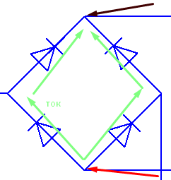
However, if one of the diodes in the breakage, the current flows along the surviving branch and conditionally operational values appear on the screen.
The third position of the probes is a red probe to the output with the “-” sign, and black to the output with the “+” sign, then the multimeter will display the same results as when checking the diode connected in the opposite direction (infinity). If the proverb worked or small values on the screen (from zero to hundreds) mean the bridge is broken.
Such verification is effective, but will not give such reliability as described in the previous paragraph of the article. If the device still does not work and there is no voltage at the output of the diode bridge, then unsolder the bridge and re-check it.
Verification by other means
If you don’t have a multimeter, but you have a Soviet tester or, as it is also called a “workshop” or some Ohmmeter with a measurement limit of up to ten kOhm, you can use these dial gauges.
The logic of the test is the same, only in the direct connection the arrow will indicate low resistance, and in the reverse connection of the diode - high.
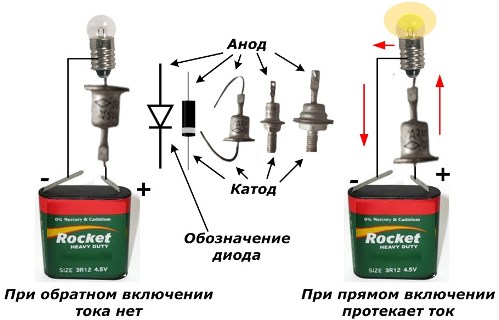
If you don’t have this either, any battery or several batteries with an output voltage of more than a couple of volts and an incandescent bulb will help you (you can use an LED and a crown, a 9V battery). Take a look at the picture and everything will become clear to you.
Conclusion
Testing a diode bridge is a basic skill for those who repair electronic equipment and electrical appliances and for those who want to learn how to do this. To do this, you need a minimal set of tools, but a good understanding of not only the verification method, but also the logic of the bridge itself.
The use of a multimeter, tseshki or prozverkov does not change the final result when properly measured. However, in my practice, it happened that the device showed the health of the diode bridge, but in reality it did not work.
Perhaps he "broke through" under a higher voltage than at the terminals of the device with which I tested. Therefore, the most accurate way to “see” the processes occurring in the circuit is to oscilloscope.
In auto electrics, for example, only the waveform of the voltage in the line can determine the health of the diode bridge of the generator, and a specialist can even determine what exactly happened - a breakdown or break.
See also at i.electricianexp.com
:
