Categories: Featured Articles » Novice electricians
Number of views: 6776
Comments on the article: 0
How sensors and clamp meters work for measuring direct and alternating current
To expand the functionality of multimeters, oscilloscopes, and other electrical measuring instruments, current sensors in the form of ticks are used - current clamps. To take measurements with clamps, they are closed into the girth of the conductor with current, and thus, without breaking the circuit and without the need to cut any shunt into the conductor, they measure.
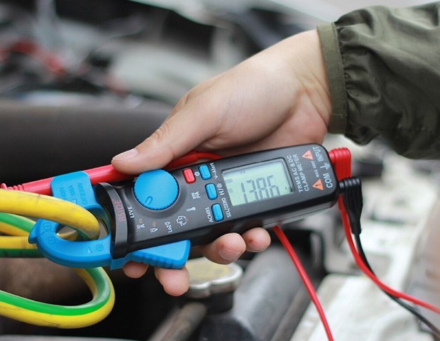
It is simple and convenient. The device displays the measurement result on its scale in the form of voltage or current proportional to the measured current value. The advantage of the method lies in the fact that the device may not have a sufficiently wide input range, while the sensor - clamps are quite able to freely accept the conductor even with a very high current.
The conductor with the measured current not only remains intact, but is always galvanically isolated from the circuits of the measuring device. The device itself can have an input circuit with a very high impedance and even be grounded. There is no need to somehow regulate or turn on and off the power of the circuit, the parameters of which are measured by clamps, which means that there will be no downtime in the operation of the powered equipment.
The rms value of the current in the frequency range of the sensor can be measured by using a current sensor with a multimeter capable of measuring rms values. In this case, the range will be limited by the capabilities (scale) of the multimeter. Best results are achieved with sensors with a wide frequency response, minimum phase shift and high accuracy.
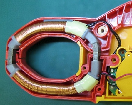
Sensors operating on the principle of conventional measuring current transformer. Any transformer has a primary and secondary windings installed on a common magnetic circuit. The primary voltage is supplied to the primary winding, an alternating magnetic flux is created in the core, inducing in the secondary winding the corresponding EMF transformation coefficient. The currents of the primary and secondary windings are correlated as the number of turns in the secondary and primary windings.
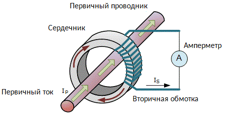
This is how the current sensor for measuring AC current works. A clamp-shaped magnetic circuit closes around the conductor. The conductor is the primary winding, consisting of one single turn, the current value in which you need to find out.
The current in the secondary winding will be proportional to the current in the conductor and differ from it by a number of times equal to the transformation coefficient, that is, as many times as many turns in the secondary winding. The number of turns in the secondary winding of the sensor is usually 1000, 500 or 100.
If the sensor has 1000 turns, then the clamps are designated 1000: 1 or 1mA / A - this means that 1 mA in the readings of the device is identical to 1A in the studied conductor. Or 1A on the device - 1000 A in the conductor.
The ratio may, in principle, be different: 3000: 5 or 2000: 2, depending on the purpose of the device. However, in most cases, ticks are paired with a conventional multimeter and the ratio is usually 1000: 1.
At a ratio of 1000: 1 or 1mA / A, the readings will be as follows. With an input current of 700A, the output will turn out to be 700mA, at 300A - 300mA, etc. This is because the output of the sensor is connected to a digital multimeter in AC current measurement mode with a selected range of values.
To determine the current value of the current in the conductor, the readings of the multimeter are multiplied by the coefficient of the sensor. The main thing is that the measuring device has the required input impedance.
If the measuring device has an input only by voltage (voltmeter or oscilloscope), then it can also be used with a current sensor - clamps. For this, the current output of the sensor must be coordinated with the input of the device, using the principle of a measuring current transformer. Then the readings of the alternating voltage will be proportional to the measured alternating current.
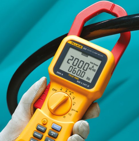
There are current clamps capable of measuring not only alternating, but also direct current. In such ticks, the principle of their operation is based on the Hall effect, when the current parameters are derived from the parameters of the magnetic field generated by it, acting on the semiconductor and initiating the Hall effect in it.
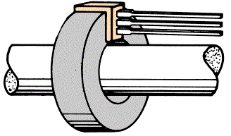
A thin plate of a semiconductor is mounted perpendicular to the magnetic field of the current to be measured. An excitation current is applied to the plate in a certain direction (let's say along it), which deviates in an external magnetic field under the action of the Lorentz force in the transverse direction, and then in this direction the emf (Hall voltage) can be measured at the edges of the plate.
With a constant excitation current through the plate, the Hall EMF, as well as the magnetic field induction of the measured current, will be proportional to the measured current. That is, the Hall voltage corresponds to the current in the conductor that passes inside the sensor magnetic circuit. Such a circuit has great advantages over devices based on a current transformer.
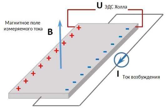
Since the generation of the Hall EMF does not depend on the direction of the magnetic induction vector, but depends only on its magnitude, a sensor based on the Hall effect measures both alternating and direct current. In addition, the sensor absolutely accurately captures the phase of the change (direction) of the magnetic field, which means it is suitable for observing the shape of the current.
Ticks with a Hall sensor come with one or two built-in sensors. Various tick models have a wide dynamic range and frequency response, signal linearity and high accuracy.
The scope of such pincers covers all equipment with a direct current of up to 1500 A without the need for embedding expensive shunts. Alternating current with a frequency of tens of kilohertz is also measurable using ticks based on the Hall effect, and the current shape can be very different, the rms value will be found.
The output signal in millivolts, proportional to the measured current, can be easily perceived by most multimeters, oscilloscopes, and recorders.
What is an ammeter, types, device and principle of operation
How to use current measuring clamps
See also at i.electricianexp.com
:
