Categories: Featured Articles » Practical Electronics
Number of views: 95831
Comments on the article: 3
Analog comparators
 Title comparators came from the Latin compare - compare. Devices in which measurement is carried out by comparing with a standard work on this principle. For example, equal-arm scales or electric potentiometers.
The principle of action distinguishes between electrical, pneumatic, optical and even mechanical comparators. The latter are used for checking end length measures. For the first time, a comparator for verifying end measures was applied in Paris by Lenoir in 1792, as there is an article in the encyclopedia of Brockhaus and Efron.
This mechanical comparator was used to check the 1m standard in the formation of the French metric system. The measurement accuracy of such a comparator using a system of movable levers reached 0.0005mm. For that time it was very accurate. But in this article we will not consider in detail mechanical and other comparators, since our task is to voltage comparators.
Integrated Comparators. Principle of action and varieties
Currently, comparators are mainly used in integrated design. Few people would think of assembling a comparator from discrete transistors. Moreover, comparators are used as part of some circuits.
For instance, integrated timer NE555 contains as many as two comparators at the inputs, which, in fact, is achieved all the charm of his work. In addition, many modern microcontrollers also have built-in comparators. But, regardless of execution, the principles of the comparators are exactly the same.
Modern comparators in the scheme are very similar to opamps. In fact, this is the same operational amplifier, only without feedback and with a very high gain. The comparator also has two inputs, direct and inverse (marked with a circle or a minus sign).
The main function of the comparator is to compare two voltages, one of which is exemplary or reference, and the other is actually measured. The output signal of the comparator can take only two values: a logical zero, and a logical unit, but cannot be changed linearly, like an operational amplifier.
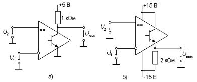
At the output of the comparators, as a rule, there is an output transistor with open collector and emitter. Therefore, it can be connected either according to a circuit with an OE or an emitter follower, depending on the requirements of a particular circuit, as shown in Figure 1.
Figure 1a shows the inclusion of an output transistor in a circuit with a common emitter. In this case, TTL and CMOS - logic with a supply voltage of + 5V can be connected to the output of the cascade. If the CMOS - logic is powered by a voltage of 15V, then the top output of the 1Kohm resistor according to the scheme should be connected to the + 15V power bus.
When the output transistor is connected according to the emitter follower circuit, as shown in Figure 1b, the voltage at the output of the comparator will vary within + 15V ... -15V. However, with this inclusion, the speed of the comparator decreases significantly, and in addition, the inputs are “swapped", - the inputs are inverted.
Picture 1.
How to check the comparator, alive or not alive?
If a LED is sequentially soldered with a resistor R in the circuit shown in Figure 1a by connecting the anode to a + 5V power supply, and voltage is applied to the inputs using resistors, then changing these voltages using at least variable resistors can cause the LED to flash. In what sequence to apply the reference and input voltage can be found further. Let such a test scheme be a small practical task.
The logic of the comparator
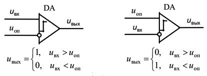
Functional diagram of the comparator is shown in Figure 2.
Figure 2. Functional diagram of the comparator
With so many inputs and input signals, two options are possible. In the first case, shown on the left side of the figure, the reference voltage is applied to the inverting input, and the input voltage to the non-inverting one. If the input voltage exceeds the reference voltage, a high level will appear at the output of the comparator (log. 1). Otherwise, we will have a logical zero.
In the second version, shown on the right side of the figure, the reference voltage is applied to the direct input, and the input voltage to the inverting one. In this case, if the input voltage is greater than the reference voltage at the output of the comparator, logic zero, otherwise, unity. In figure 2, all these conclusions are shown in the form of mathematical formulas.
But here an attentive reader may have a fair question: “Look at Figure 1, how many outlets there are! So which one is they talking about, what kind of zero is there, and where is the unit here? ” In this case, we are talking about the base of the output transistor, it is believed that this is the output of the operational amplifier, to which the input signals are supplied. And the output transistor, as indicated in the comments to Figure 1, can be turned on in any way.
Some characteristics of analog comparators
When using comparators, their characteristics must be taken into account, which can be divided into static and dynamic. The static parameters of the comparator are those that are determined in steady state.
First of all, this is the threshold sensitivity of the comparator. It is defined as the minimum difference of the input signals at which a logical signal appears at the output.
In addition to input and output, many comparators have outputs for supplying bias voltage Ucm. Using this voltage, the necessary shift of the transfer characteristic relative to the ideal position is carried out.
One of the main parameters of the comparator is hysteresis. The easiest way to explain this phenomenon is to use the example with a conventional relay. Let the operating voltage of the coil, for example, 12V, then it is with it that the relay will operate. If after that, gradually reduce the supply voltage of the coil, then the relay will release, for example, at a voltage of 7V. This difference of as much as 5V for this relay is hysteresis. But the relay will not turn on again, if the voltage remains at the 7V level, it will not happen. To do this, raise the voltage again to 12V. And then ...
The same is observed with comparators. Suppose that the input voltage rises smoothly relative to the reference voltage (signals are applied, as shown in the left part of Figure 2). As soon as the input voltage becomes higher than the reference voltage (no less than the threshold sensitivity value), a logical unit will appear at the output of the comparator.
If the input voltage now begins to decrease smoothly, then the transition from a logical unit to a logical zero will occur when the input voltage is slightly lower than the reference voltage. The difference in input voltages at these “above the reference” and “below the reference” is called the hysteresis of the comparator. The hysteresis of the comparator is due to the presence of positive feedback in it, which is designed to suppress the "bounce" of the output signal when switching the comparator.
How is the comparator
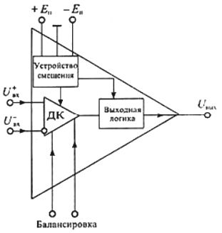
The circuit diagram at the transistor level is quite complex, large, not very clear, but practically not needed. These are the design features of integrated circuitry, it seems that transistors stick out everywhere, even where not needed. Therefore, it is better to consider a simplified functional diagram of the comparator, which is shown in Figure 3.
Figure 3. Simplified functional diagram of the comparator
The diagram shows the input differential stage (DC), the output logic, and the level shift circuit.
The input DC carries out the main amplification of the difference signal, and also, with the help of a bias device, it makes it possible to carry out the preferred state at the output, which allows you to choose the type of logic (TTL, ESL, CMOS) that you have to work with.This setting is carried out using a trimming resistor connected to the terminals "balancing".
Gating and memory comparators
Some modern comparators have a gating input: the comparison of input signals occurs only at the moment of supply of the corresponding pulse. This allows you to compare the input signals at that moment in time when it is required. Well, right, whatever you like! A simplified block diagram of a comparator with gating is shown in Figure 4.
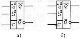
Figure 4. Simplified block diagram of a comparator
The comparators shown in this figure have a paraphase output, like a trigger, the upper output is direct, and the lower, marked with a circle, is naturally inverse. In addition, gate C is also shown here.
In Fig. 4a, the input signals are gated at a high level at input C. When gating at a low level, the graphic designation at input C should have a small circle (inversion sign).
In Fig. 4b, the gate input C has a dash /, which indicates that the gating occurs on the rising edge of the pulse. In the case of gating on a falling front, the dash has this direction.
Thus, the gating signal is nothing but the resolution of the comparison. The result of the comparison can appear at the output only during the action of the gate pulse. But some comparator models have memory (just one trigger is enough for this) and remember the comparison result until the next gating pulse arrives.
The duration of the strobe pulse (its edge) must be sufficient for the input signal to pass through the DC before the memory cell has time to trigger. The use of gating increases the noise immunity of the comparator, since interference can change the state of the comparator only in a short time gating pulse. Often, the comparator is called a single-bit ADC.
Classification of Comparators
By a combination of parameters, comparators can be divided into three large groups. These are general purpose comparators, high speed and precision. In amateur practice, the former are most often used.
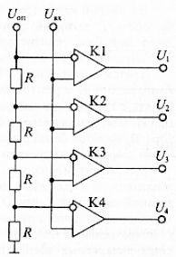
Not having any supernatural parameters for speed and gain, the presence of gating and memory, comparators of wide application have their own attractive properties and features. They have low power consumption, the ability to work at low voltage, and the fact that up to four comparators can be placed in one case. Such a "family" allows in some cases to create very useful devices. One of these devices is shown in Figure 5.
This is the simplest converter of an analog signal into a digital unitary code. Such a code can be converted into binary using digital conversion.
Figure 5. Scheme of converting an analog signal to a digital unitary code
The circuit contains four comparators K1 ... K4. The reference voltage is applied to the inverting inputs through resistive divider. If the resistance of the resistors is the same, then the voltage at the inverting inputs of the comparators will be n * Uop / 4, where n is the serial number of the comparator. Input voltage is applied to the non-inverting inputs connected together. As a result of comparing the input voltage with the reference voltage at the outputs of the comparators, we get a unitary digital code of the input voltage.
In more detail, we will consider the parameters of general-purpose comparators using the example of the widespread and fairly affordable comparator LM311.
LM311 Series Comparators
Supply voltages and working conditions
As written in the Data Sheet, these comparators have input currents a thousand times smaller than comparators of the LM106 or LM170 series. In addition, the LM311 series comparators have a wider range of supply voltages: from bipolar ± 15V, as in operational amplifiers, to unipolar + 5 ... 15V.This wide power range allows the use of the LM311 series comparators in conjunction with operational amplifiers, as well as with various series of logic circuits: TTL, CMOS, DTL and others.
In addition, the LM311 comparators can directly control the lamps and relay windings with operating voltages up to 50V and currents not exceeding 50mA. In addition to the LM311, there are also comparators LM111 and LM211. These microcircuits differ in operating conditions, mainly in temperature. The operating range of the LM311 is 0 ° C ... + 70 ° C (commercial range) LM211 -25 ° C ... + 85 ° C (industrial), LM311 -55 ° C ... + 125 ° C (military acceptance).
Full domestic analogs of the LM311 comparator are 521CA3, 554CA3 and some others. When replacing, you do not need to change the circuit and do not even have to redo the circuit board. You should only pay attention to the fact that comparators, like other microcircuits, are available in various cases, so when you buy them you should pay maximum attention to this, especially if this purchase will be used to repair the finished device.
Figure 7 shows the pinout (pinout) of the LM311 comparator, made in various cases.
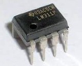
Figure 6. Comparator LM311

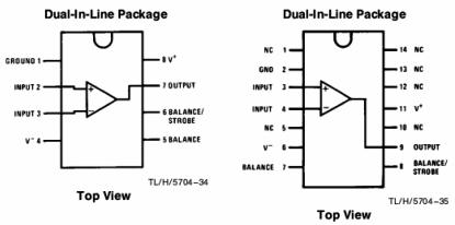
Figure 7. Pinout (pinout) of the LM311 comparator, made in various cases.
Actually, much more can be written about comparators. With their help you can do photo relay, thermal relay, electric field indicator, capacitive relay and many other useful devices.
Several interesting and useful circuits can be found in the "datasheet" of the LM311 comparator, where they are given as typical switching circuits. It is in this form that comparators are used quite often. Here are just descriptions of typical schemes given in "typical", English. But even without knowing a foreign language, you can figure it out, at least with the help of an online translator Google.
Continued article: Some simple comparator circuits
Boris Aladyshkin
See also at i.electricianexp.com
:

