Categories: Featured Articles » Practical Electronics
Number of views: 27920
Comments on the article: 0
Operational amplifiers - types, designations, amplifier enclosures
A bit of history
 First, a few words about what operational amplifiers (op amps) are. The name itself suggests that some operations are performed with their help. Could it be a surgical instrument? Not at all. This tool is designed to perform various mathematical operations.
Initially, operational amplifiers were used in analog computers (AVMs), in which information was represented by continuous signals in the form of currents and voltages.
Although AVMs are now a thing of the past, analog signalsobtained from various sensors (for example, fluid pressure or the angle of rotation of the gas pedal) are still used very widely. And there’s simply nowhere to go from this.
Most often, analog signals are converted to digital using, for example, an ADC, and their further processing is performed digitally using microprocessors or microcontrollers.
Lamp Operational Amplifiers
First, still tube AVMs, mathematical operations on analog data were performed using special circuits, which were called operational amplifiers. Naturally, the first operational amplifiers were tube amplifiers. Their appearance and diagram are shown in Figures 1 and 2.
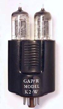
Picture 1.
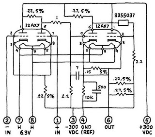
Figure 2
The design of the operational amplifier is clear from the figure: the entire circuit was assembled in one housing and simply inserted into the socket using an octal base as a single lamp. The elemental base, as follows from Figure 2, is a pair of lamps - double triodes. As if only 4 transistors.
Transistor Operational Amplifiers
After the advent of transistors, operational amplifiers began to be implemented in the form of boards with connectors, and this state of affairs continued until integrated circuits were invented. This somewhat improved the general state of affairs, deprived the circuit of all the “tube” drawbacks: high power consumption and low reliability due to the limited lamp life. But transistor op amps had their drawbacks. First of all, their dimensions were quite large, I would like less.
Integrated Operational Amplifiers
The first integrated operational amplifier µA702 was developed in 1963 by Robert Widlar, a Fairchild Semiconductor employee. The device contained only 9 transistors, but it cost as much as $ 300, which allowed it to be used only in developments for the military industry. But overall, it was a huge step forward, one of the greatest discoveries in electronics.
Already in 1965, Robert Widlar designed the µA709 operational amplifier, which cost much less to manufacture, for only $ 10. And even such a price did not allow it to be used for household appliances, but was quite acceptable for industrial automation, etc. tasks.
In 1967, Widlar joined the National Semiconductor, where under his leadership they developed the LM101, which had the best characteristics. In 1968, Fairchild released the µA741, which had internal frequency correction, which made its operation even more stable - an operational amplifier with internal correction is not prone to self-excitation.
As already said The main purpose of the operational amplifier is to perform mathematical operations on analog variables represented by voltages (summation, integration, multiplication, etc.). But later it became clear that the op-amp is a very universal element, and its application is simply limitless: signal amplification, active frequency filters, generators, comparators and much more.
Now operational amplifiers are produced in such quantities that it is simply impossible to do without their use. In addition, the price of these electronic products is in some cases very low, and the possibilities are very high. Several operational amplifiers are already housed in one case, micro-power consumption and a very low level of internal noise bring real amplifiers closer to ideal ones. All this allows the use of operational amplifiers even in professional sound equipment (multichannel mixers), making them simply irreplaceable.
Of course, the history of the appearance and development of operational amplifiers is much longer and, probably, more interesting, but for now we will limit ourselves to this information.
Operational Amplifier Symbols
Or a story about triangles and rectangles
The first steps in amateur radio begin, as a rule, with the use of discrete transistors, which, often with some irony or, on the contrary, respect, experienced experts simply call "loose". You can do almost anything with such transistors, but often this activity requires a fairly high qualification of the performer.
A simple example: tuning a high-quality UMZCH can cost several sets of powerful expensive transistors. To prevent this from happening, you must have sufficient experience building such devices, use various protective devices in the power and load circuits. In the simplest case, incandescent lamps of the corresponding voltage and power.
Much faster than the final results on the basis of "amplifier" can be achieved if you use the ULF in the integrated performance. Just added a few resistors, capacitors, a power supply, a timbral block, and please, before you ready amplifier. But here we will talk about operational amplifiers, their use in amateur radio designs.
Probably no one will collect at home AVM and all sorts of adders - differentiators. A very widespread use of op-amps in amplifiers, mixers, and just when repairing various electronic equipment will require at least basic knowledge about operational amplifiers. What will be written about in this article.
How operational amplifiers are indicated on electrical circuits
Like all radio parts of operational amplifiers are indicated on the diagrams using UGO - conventional graphic symbols. Designations can be very diverse, although, in general, they mean the same thing. At the first acquaintance with circuits on operational amplifiers, doubts arise, suddenly I will do something wrong, suddenly everything will simply burn out.
If you do not take into account the internal structure of operational amplifiers, by the way, which is rather complicated at first glance (these are the traditions of integrated electronics), outwardly the operatives look simple and logical. The further description will concern just the external conclusions and their use in various schemes.
A modern operational amplifier usually has two inputs, one output and two outputs for connecting power. This is the minimum "gentlemanly" set. In addition to the above conclusions, there may be conclusions for connecting frequency correction elements, conclusions for balancing (zero adjustment at the output). Various UGOs for operational amplifiers are shown in Figure 1. Consider them as detailed as possible.
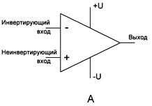
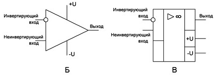
Figure 3
In Figures 1a and 1b, the cases of the operational amplifier are shown in the form of an isosceles triangle. Yes, this is nothing more than a microcircuit case. On the left side there are 2 inputs: inverting (indicated by a minus sign or a small circle) and non-inverting (indicated by a plus sign or simply drawn without a circle). Note: if the circuit is drawn according to the “rules of good tone”, then all the inputs are on the left, and the outputs are on the right of the element in question.Auxiliary conclusions, for example, correction, nutrition, can be located as you like.
Here, just in the right corner of the triangle there is an output with the inscription "Output", and the terminals for connecting the power, most often two polar, are shown above and below. In order not to overload, do not fog up the circuit conclusions, power supplies are most often not shown. Their accession is indicated simply in the notes to the scheme.
The case of the operational amplifier can be depicted as a rectangle, as shown in Figure 1c. All other parts of this figure are the same as in the case of a triangular case.
Enclosures for operational amplifiers
Modern semiconductor technology has achieved such advances that the number of semiconductor structures in one enclosure simply cannot be counted. It is enough to recall modern microprocessors, the number of transistors in which amounts to billions of pieces. Therefore, it’s even very simple to place several operational amplifiers in one case containing just a few dozen transistors.
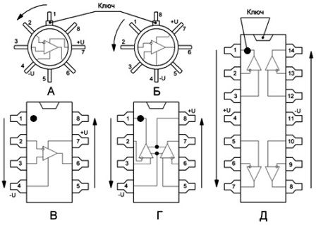
Figure 4
The location of the terminals of the operational amplifiers of various types in the same cases is the same, which makes it very easy to replace them, especially in cases where the operational amplifiers are installed in connectors - sockets. But at the same time, operational amplifiers of the same type can be manufactured in completely different cases. This variety is required in conditions of mass and large-scale production mainly for the convenience of developing printed circuit boards and the entire design of an electronic device.
Figure 3 shows the operational amplifiers made in the DIP8, DIP14 cases.
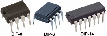
Figure 5
Figure 4 shows a 4558 type operational amplifier in a SIP-8 type enclosure — a single-row eight-pin enclosure.
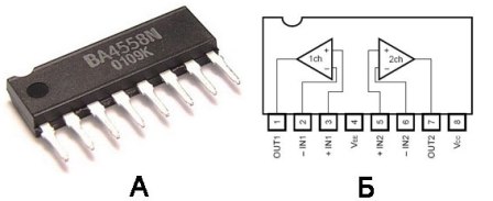
Figure 6
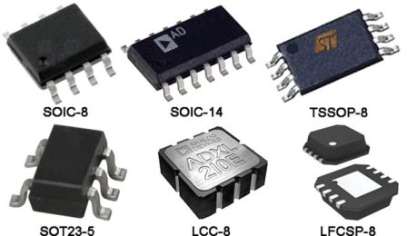
Currently, operational amplifiers in SMD enclosures are gaining increasing popularity.
Figure 7
In the next article, we will consider the ideal operational amplifier, its inputs and outputs, and some basic properties that are useful in the process of independent development and manufacturing (read just soldering at your leisure) of various schemes "for the soul". And it’s really good if the soldering process is replaced solderless breadboardsabout which the article has already been.
Continuation of the article:The ideal operational amplifier
Boris Aladyshkin
See also at bgv.electricianexp.com
:

