Categories: Featured Articles » Practical Electronics
Number of views: 20569
Comments on the article: 0
Voltage divider for resistors, capacitors and inductors
In order to obtain a fixed voltage value equal to a fraction of the initial value, voltage dividers are used in electrical circuits. Voltage dividers can consist of two or more elements, which can be resistors or reactances (capacitors or inductors).
Voltage divider - a combination of resistances, used to divide the input voltage into parts.
In its simplest form, the voltage divider is represented by a pair of sections of an electric circuit connected in series with each other, which are called the shoulders of the divider. The upper arm is the section that is located between the point of positive voltage and the selected connection point of the sections, and the lower arm is the section between the connection point (selected point, zero point) and the common wire.
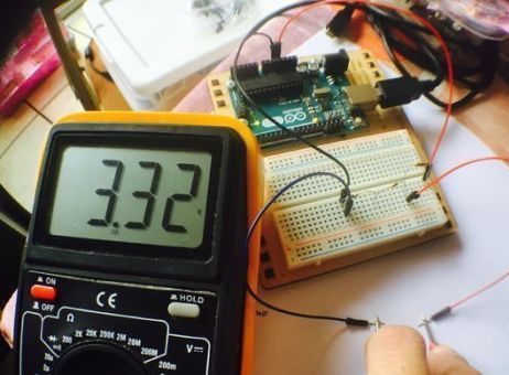
Resistor voltage dividers
Of course, voltage dividers can be used both in direct current circuits and in alternating current circuits. Resistor dividers are suitable for both circuits, but they are only used in low voltage circuits. To power the devices, voltage dividers on the resistors are not used.
In its simplest form, a resistive voltage divider consists of only pairs of resistorsconnected in series. The divisible voltage is supplied to the divider, as a result, a certain fraction of this voltage, proportional to the value of the resistor, drops on each resistor. The sum of the voltage drops here is equal to the voltage supplied to the divider.
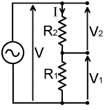
According to Ohm's law for a section of an electrical circuit, on each resistor, the voltage drop will be directly proportional to the current and the resistance value of the resistor. And according to the first rule of Kirchhoff, the current through this circuit will be the same everywhere. So, for each resistor there will be voltage drops:
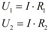
And the voltage at the ends of the circuit will be equal to:

And the current in the divider circuit will be:
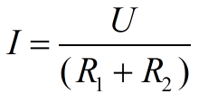
Now, if we substitute the expression for the current into the formulas for the voltage drops across the resistors, we obtain the formulas for finding the voltage values on each of the resistors of the divider:
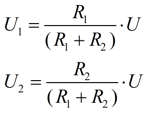
Selecting the values of the resistances R1 and R2, you can select any part of the entire input voltage. In the case when the voltage needs to be divided into several parts, several resistances are connected in series with the voltage source.
Using a voltage divider on resistors for various purposes, it is important to understand that the load attached to one of the arms of the divider, whether it is a measuring device or something else, must have its own resistance much larger than the total resistance of the resistors forming the divider. Otherwise, the load resistance itself should be taken into account in the calculations, being considered as a parallel to the shoulder resistor, which is part of the divider.
Example: there is a DC voltage source of 5 volts, it is necessary to select resistors for it for a voltage divider in order to remove a measuring signal of 2 volts from the divider. Allowable power dissipated on the divider must not exceed 0.02 watts.
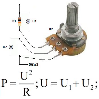
Solution: Let the maximum power dissipated by the divider be 0.02 W, then we will find the minimum total resistance of the divider at 5 volts from Ohm's law, it will turn out to be 1250 Ohms. Let 1.47 kOhm be the total resistance of the divider chosen by us, then 2 volts will fall at 588 ohms. We choose a constant resistor at 470 ohms and a variable at 1 kOhm. Set the variable resistor to 588 ohms.
Voltage divider resistors are widely used today in electronic circuits.In these schemes, the values of the resistors for the dividers are selected based on the parameters of the active elements of the circuits. As a rule, dividers are in the measuring circuits of the circuits, in the feedback circuits of voltage converters, etc. The minus of such solutions is that the resistors dissipate power in themselves in the form of heat, but the expediency justifies these small energy losses.
Capacitor voltage dividers
In alternating current circuits, in high-voltage circuits, voltage dividers are used on capacitors. It uses the reactive nature of the capacitor resistance in AC circuits. The magnitude of the reactance of a capacitor in an alternating current circuit depends on the capacitance of the capacitor and on the voltage frequency. Here is the formula for finding this resistance:
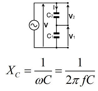
The formula indicates that the higher the electric capacity of the capacitor - the lower its reactive (capacitive) resistance and the higher the frequency - the lower the reactance. Such dividers are used in measuring circuits of AC circuits, voltage drops on the shoulders are considered similar to the case with constant active resistances (resistors, see above).
The advantage of the capacitors used in dividers is that the dissipation of energy in the form of heat is minimal, and depends only on the quality of the dielectric.
Inductor Voltage Divider
Inductive voltage divider is another type of divider used in measuring electronics of alternating current, especially in low-voltage circuits operating at high frequencies. The resistance of the coils for alternating current of high frequency is mainly reactive (inductive) in nature, it is found by the formula:
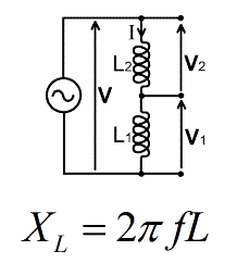
The formula indicates that the higher the inductance and the higher the frequency, the higher the coil resistance to alternating current. It is important to understand that the coil wire has an active resistance, so the power dissipated in the form of heat, which is characteristic of the divider on inductors, is much higher than that of dividers on capacitors.
In amateur electronics, voltage dividers are often used. when connecting analog sensors to Arduino modules.
See also at i.electricianexp.com
:
