Categories: Featured Articles » Practical Electronics
Number of views: 23792
Comments on the article: 0
Feedback operational amplifier circuitry
Comparators
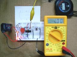 If you use an operational amplifier without negative feedback (OOS), then we can definitely say what happens comparator. In order to understand how it works, you can do some simple, but visual experiments. You will need a little for this: the operational amplifier itself, a power supply with a voltage of 9 ... 25V, several resistors, a pair of LEDs and a voltmeter (digital multimeter).
The simplest logic probe is assembled from LEDs and resistors, as shown in Figure 1.
When a positive voltage is applied to the probe input (you can even supply + U), the red LED lights up, and if the input is connected to a common wire, the green one lights up. With the help of such a probe, the output state of the tested operational amplifier becomes clear and understandable.
As an experimental “rabbit,” any one that is not very high-quality and expensive is suitable operational amplifier, for example, KR140UD608 (708) in plastic cases or K140UD6 (7) in round metal.
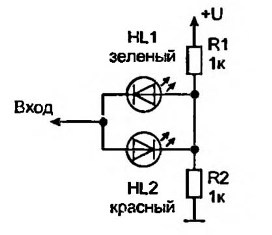
Figure 1. Scheme of a simple logical probe
It should be noted that despite the different cases, the pinout of these microcircuits is the same and corresponds to that shown in the diagrams below. It often happens that the pinout of plastic and metal cases does not match, although in fact they are the same microcircuits. Now most of the operational amplifiers, especially imported ones, are available in plastic cases, and everything works well and perfectly, and there is no confusion with the pinouts. And before, such “plastic” microcircuits were contemptuously called “consumer goods” by specialists.
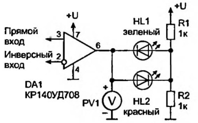
Figure 2. Scheme on an operational amplifier
For the first experiments, we assemble the circuit shown in Figure 2. Not much has been done here: the operational amplifier itself and the logical probe shown in Figure 1 are connected to a unipolar power source. Supply voltage + U unipolar 9 ... 30V. The magnitude of the stress in our experiments is not of particular importance.
Here a completely legitimate question may arise: “Why is the probe logical, because the operational amplifier is an analog element?” Yes, but in this case, the operational amplifier does not work in gain mode, but in comparator mode, and it has only two levels of output. A voltage close to 0V is called a logical zero, and a voltage close to + U is a logical unit. In the case of bipolar power, a voltage close to –U corresponds to a logical zero.
When applying a supply voltage, one of the LEDs must be lit. It is impossible to answer the question of which, red or green, since everything depends on the parameters of a particular operational amplifier and on external conditions, for example, network interference. If you take several of the same type of op-amp, then the results will be very different.
The voltage at the output of the operational amplifier is controlled by a voltmeter: if the red LED is on, the voltmeter will show a voltage close to + U, and if the green LED is lit, the voltage will be almost zero.
Now you can try to apply some voltage to the inputs and look at the indicators and voltmeter how the operational amplifier will behave. The easiest way is to apply voltage by touching one finger in turn of each input of the operational amplifier, and the other of one of the power pins. In this case, the glow of the probe and the voltmeter reading should change. But these changes may not occur.
The thing is that some operational amplifiers are designed for the input voltage to be within certain limits: slightly higher than the voltage at terminal 4 and slightly lower than the supply voltage at terminal 7. This is “somewhat lower, higher” is 1 ... 2B. To continue the experiments, having fulfilled the indicated condition, it will be necessary to assemble a slightly more complex scheme, shown in Figure 3.
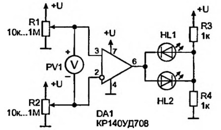
Figure 3 Feedback amplifier operational circuitry
Now the voltage is supplied to the inputs using variable resistors R1, R2, the motors of which should be installed near the middle position before starting the measurements. The voltmeter has now moved to another place: it will show the voltage difference between the direct and inverse inputs.
It is better if this voltmeter is digital: the polarity of the voltage can change, a minus sign will appear on the indicator of the digital device, and the pointer device will simply “roll over” in the opposite direction. (You can use a pointer voltmeter with a midpoint on the scale.) In addition, the input resistance of a digital voltmeter is much higher than that of a pointer, so the measurement results will be more accurate. The output status will be determined by the LED indicator.
It is appropriate to give such advice: it is better to do these simple experiments with your own hands, and not just read and decide that everything is simple and clear. This is how to read the guitar tutorial, while never picking up the guitar. So, let's begin.
The first thing to do is set the variable resistor motors to about the middle position, while the voltage at the inputs of the operational amplifier is close to half the supply voltage. The sensitivity of the voltmeter should be maximized, but perhaps not immediately, but gradually, so as not to burn the device.
Suppose that the output of the operational amplifier is low, the green LED is on. If this is not so, then this state can be achieved by rotating the variable resistor R1 in such a way that the engine moves down the circuit - it can be practically up to 0V.
Now, using the variable resistor R1, we begin to add voltage to the direct input of the operational amplifier (pin 3), observing the voltmeter readings. As soon as the voltmeter shows a positive voltage (the voltage at the direct input (terminal 3) is greater than that at the inverse (terminal 2)), the red LED will light. Therefore, the voltage at the output of the operational amplifier is high or, as previously agreed, a logical unit.
A little help
More precisely, not even a logical unit, but a high level: a logical unit indicates the truth of the signal, they say, an event has occurred. But this truth, this logical unit can be expressed and low level. As an example, we can recall the RS-232 interface, in which a negative voltage corresponds to a logical unit, while a logical zero has a positive voltage. Although in other schemes, the logical unit is most often expressed in a high level.
We continue our scientific experience. We begin to carefully and slowly rotate the resistor R1 in the opposite direction, following the voltmeter. At a certain point, it will show zero, but the red LED will still light. It is unlikely to catch a position in which both LEDs are off.
With further rotation of the resistor, the polarity of the voltmeter readings will also change to negative. This suggests that the voltage at the inverse input (2) in absolute value is higher than at the direct input (3). The green LED lights up, indicating a low level at the output of the operational amplifier. After that, you can continue to rotate the resistor R1 in the same direction, but no changes will occur: the green LED will not go out and will not even change the brightness at all.
This phenomenon occurs when the operational amplifier is in comparator mode, i.e. without negative feedback (sometimes even with PIC).If the op-amp operates in linear mode, is covered by negative feedback (OOS), then when the resistor R1 engine rotates, the output voltage changes in proportion to the rotation angle, read the voltage difference at the inputs, and not at all a step. In this case, the brightness of the LED can be changed smoothly.
From all the above, we can conclude: the voltage at the output of the operational amplifier depends on the difference in voltage at the inputs. In the case where the voltage at the direct input is higher than at the inverse, the output voltage is high. Otherwise (the voltage on the inverse is higher than on the direct one), the output level is a logical zero.
At the very beginning of this experiment, it was recommended to install the resistor motors R1, R2 approximately in the middle position. And what will happen if you initially set them to a third of the turnover or two-thirds? Yes, actually nothing will change, everything will work the same way as described above. From this we can conclude that the signal at the output of the operational amplifier does not depend on the absolute value of the voltages at the direct and inverse inputs. And it depends only on the voltage difference.
From all that has been said, one more important conclusion can be drawn: an operational amplifier without feedback is a comparator - a comparator. In this case, the reference or reference voltage is applied to one input, and the voltage, the value of which must be controlled, to the other. Which input to supply the reference voltage is decided during the development of the circuit.
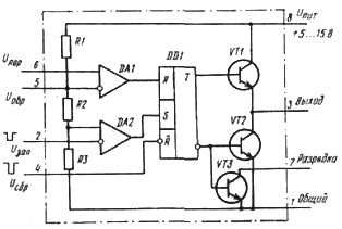
As an example, Figure 4 shows a diagram. integrated timer NE555at the input of which there are immediately 2 internal comparators DA1 and DA2.
Figure 4Integrated Timer Circuit NE555
Their purpose is to manage the internal RS trigger. The control logic is quite simple: the logical unit from the output of the comparator DA2 sets the trigger to one, and the logical unit from the output of the comparator DA1 resets the trigger.
A divider is assembled on resistors R1 ... R3, which supplies reference voltages to the inputs of the comparators. All three resistors have the same resistance (5K), forming 2/3 and 1/3 of the supply voltage, which are supplied, respectively, to the inverting input DA1 and to the non-inverting input DA2.
In terms of what was written above, it turns out that the logical unit at the output of the comparator DA1 will be obtained if the input voltage at the direct input exceeds the reference voltage at the inverse (2 / 3Upit), the trigger will reset to zero.
In order to set the trigger to 1, you need to get a high level at the output of the internal comparator DA2. This condition will be achieved when the voltage level at the inverted input DA2 is less than 1 / 3Upit. It is such a reference voltage applied to the direct input of the comparator DA2.
Here the goal of the description of the NE555 integrated timer is not set, just as an example of using the op-amp, input comparators are shown hidden inside the microcircuit. For those who are interested in using the 555 timer, you can recommend reading the article "Integrated timer NE555".
See also: Feedback Operational Amplifier Circuits
Boris Aladyshkin
See also at bgv.electricianexp.com
:

