Categories: Featured Articles » Practical Electronics
Number of views: 35233
Comments on the article: 0
Legendary Analog Chips
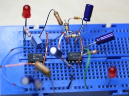 Among the many chips presented on the modern market of microelectronic components, there are real legends that have rightfully earned their high reputation. In this article, we will focus on four such legendary analog microcircuits, namely: NE555, A741, TL431, and LM311.
Integrated Timer NE555
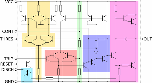
Analog integrated circuit NE555 is a universal timer. It successfully serves in many modern electronic circuits to produce repetitive or single pulses with constant time characteristics. The chip is essentially asynchronous RS triggerhaving specific input thresholds that are precisely defined by internal analog comparators and an accurate voltage divider.
The integrated structure of the microcircuit includes 23 transistors, 16 resistors and 2 diodes. NE555 is still available in various packages, but it is most popular in DIP-8 and SO-8 cases, and it is in this form that it can be found on many boards. Domestic manufacturers produce analogues of this timer under the name KR1006VI1.
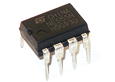
The history of the NE555 chip begins in 1970, when Hans Kamensind, an employee of the American microelectronic company Signetics, a specialist in PLL circuits, debugged a PLL with a VCO, whose frequency was now independent of voltage, fired due to the economic crisis.
This development was later called NE566, and contained all the elements of the future NE555 timer, including comparators, voltage dividertrigger and key. The circuit could generate triangular pulses with the amplitude set by the internal divider, and with the frequency set by the external RC circuit.
Hans Kamensind sold his development to Signetics, and then offered to refine it to the waiting multivibrator - a single pulse generator. The idea was not immediately supported, but Signetics' sales manager, Art Fury, insisted, and the project was approved, the future chip was called NE555 (NE from SigNEtics).
Refinement and debugging of the timer took several more months, and finally in 1971, sales of NE555 in an eight-pin case started at a price of 75 cents. Today, functional analogues of the original NE555 are available in a variety of bipolar and CMOS versions by almost all major manufacturers of electronic components.
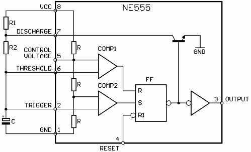
Now consider the purpose of the conclusions of the NE555 integrated timer, this will allow the reader to understand the reason why this chip has gained enormous popularity both among specialists and among amateur radio enthusiasts.
-
The first conclusion is the earth. It is connected to the negative wire of the power source.
-
The second conclusion is the trigger. When the voltage at this pin is lower than 1/3 of the supply voltage, the timer starts. At the same time, the current consumed by this input does not exceed 500 nA.
-
The third conclusion is the way out. When the timer is on, the voltage at this terminal is 1.7 volts less than the supply voltage, and the maximum current of this terminal reaches 200 mA.
-
The fourth conclusion is reset. When a low level voltage is supplied to this output, below 0.7 volts, the microcircuit returns to its original state. If a reset during operation in the circuit is not required, this output is simply connected to the plus of the microcircuit's power source.
-
The fifth conclusion is control. This output is under reference voltage, and is connected to the inverting input of the first comparator.
-
The sixth conclusion is the threshold, stop. When a voltage higher than 2/3 of the supply voltage is supplied to this output, the timer will stop and its output will be put into a rest state.
-
The seventh conclusion is discharge. When the output level of the microcircuit is low, this pin inside the microcircuit is connected to the ground, and when the output of the microcircuit is high, this pin is disconnected from the ground. This pin is capable of withstanding currents up to 200 mA.
-
The eighth conclusion is nutrition. This pin is connected to the positive wire of the microcircuit's power source, the voltage of which can be from 4.5 to 16 volts.
The NE555 chip has been widely used due to its versatility. On its basis, generators, modulators, time relays, threshold devices and many other nodes of various electronic equipment are built, the variety of which is limited only by the imagination and creative approach of engineers and developers.
Examples of tasks to be solved are: the function of restoring a digital signal distorted in communication lines, chattering filters, switching power supplies, on-off controllers in automatic control systems, PWM controllers, timers, and much more.
Additional materials about the chip NE555:
555 Integrated Timer - Travel through the Data sheet
Water leakage protection block
PWM - controller based on the NE555 integrated timer for dimming LEDs
Operational amplifier uA741
uA741 is an operational amplifier based on bipolar transistors. This second-generation operational amplifier, developed in 1968 by Fairchild Semiconductor engineer David Fullagar, is a modification of the LM101 operational amplifier, which required an external frequency correction capacitor. By uA741, an external capacitor was no longer required, because here it is immediately installed on the chip itself.
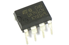
The characteristics of the uA741 were perfect for that time, and the ease of use of the microcircuit contributed to its widespread use. So uA741 has become a universal standard operational amplifier, and to this day its analogues are produced by many manufacturers of microelectronic components, for example: AD741, LM741, and the domestic analogue - K140UD7. These microcircuits are available both in DIP and chip packages.
At the heart of operational amplifiers is the same principle, the differences are only in structure. The operational amplifiers of the second and next generations include the following functional blocks:
-
The input stage is a differential amplifier that provides amplification at a high input impedance and at a low noise level.
-
High-voltage amplifier, frequency response decreases as in a single-pole low-pass filter. This is not a differential, the only way out.
-
The output stage (amplifier), which gives high load capacity, low output resistance, and provides protection against short circuit and limitation of the output current.
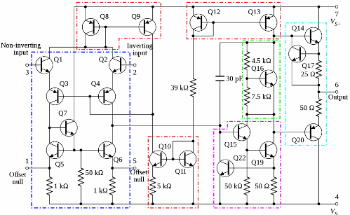
An integrated 30 pF capacitor provides frequency-dependent negative feedback that increases the stability of the operational amplifier when working with external feedback. This is the so-called Miller compensation, which functions almost like an integrator built on an operational amplifier. Frequency compensation gives the operational amplifier unconditional stability in a wide range of conditions and thereby simplifies its use in a wide range of electronic devices.
In the output stage uA741 there is a resistor with a resistance of 25 ohms, which serves as a current sensor. Together with transistor Q17, this resistor limits the current of the emitter follower Q14 to about 25 mA. In the lower arm of the push-pull output stage, current limitation through the Q20 transistor is carried out by current measurement through the emitter of the transistor Q19 and the subsequent limitation of the current flowing to the base of Q15. In more modern modifications of the uA741 circuitry, methods for limiting the output current that are slightly different from those described here can be used.
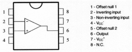
The chip has two Offset outputs for balancing, allowing you to adjust the input bias of the operational amplifier to exactly zero. An external potentiometer can be used for this purpose. The supply voltage of the microcircuit can reach from + -18 to + -22 volts, depending on the modification, however, the recommended range is from + -5 to + -15 volts.
See also on this topic:
What are operational amplifiers
Feedback operational amplifier circuitry
Feedback Operational Amplifier Circuits
Adjustable voltage regulator TL431
The TL431 was launched by Texas Instruments in 1978, and was positioned as a precision adjustable voltage regulator. The previous version was a less accurate TL430 chip. Today, TL431 is produced by many manufacturers under the markings: LM431, KA431, and its domestic counterpart - KR142EN19A.
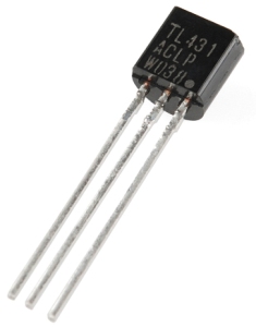
The TL431 is essentially a controlled zener diode, which is often found in the three-pin TO-92 package. This chip can perhaps be seen on the board of any of the modern switching power supplies, at least - in the scheme of galvanic isolation of secondary circuits.
The microcircuit is quite simply regulated: when a voltage of 2.5 volts is applied to the control electrode, the internal transistor, which performs the function of a zener diode, goes into a conducting state.
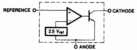
The meaning of the findings is obvious from the flowchart:
-
The first conclusion is the control electrode.
-
The second conclusion - carries the function of the anode of the zener diode.
-
The third conclusion - plays the role of the cathode of the zener diode.
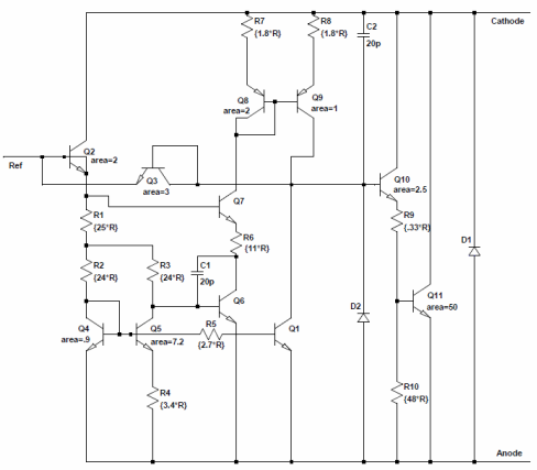
The operating voltage at the cathode can be in the range from 2.5 to 36 volts, and the current in the conducting state should not exceed 100 mA, while the control current does not exceed 4 μA. The internal voltage reference has a nominal value of 2.5 volts.
The microcircuit is so easy to configure and use that it has already found the widest application in various electronic devices, starting with switching power supplies, where it traditionally works in conjunction with an optocoupler, ending with light and temperature sensors.
Today it is difficult to find a household appliance, wherever there is a TL431, for this reason this chip is available in many different cases. Thus, TL431 is great for building feedback circuits in completely different aspects of this concept.
Chip Usage Examples TL431:
Indicators and signaling devices on an adjustable zener diode TL431
Analog Comparator LM311
The LM311 analog comparator has been manufactured by National Semiconductor since 1973 (since September 23, 2011, the company has officially been part of Texas Instruments). The domestic analogue of this comparator is KR554CA3.
This integrated voltage comparator is characterized by a very small input current (150 nA). It is specially designed for use in a wide range of supply voltages: from standard + - 15V to unipolar + 5V, traditional for digital logic. The comparator output is compatible with TTL, RTL, DTL and MOS levels.
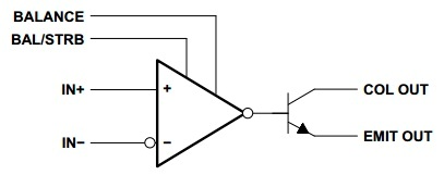
Its output stage with an open collector allows you to directly load the output to a relay or an incandescent lamp, and switch current up to 50 mA at a voltage of up to 50 V. The power consumption of the microcircuit is only 135 mW with a voltage of + -15 V. The data on the LM311 comparator is shown many typical schemes of its applications.
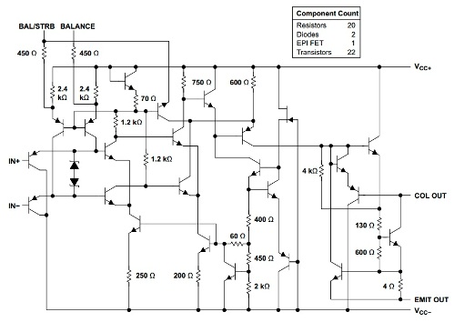
The microcircuit contains 20 resistors, 22 bipolar transistors, 1 field effect transistor and 2 diodes. The LM311 input and output can be isolated from the circuit ground so that the output circuit of the microcircuit operates on a grounded load or on a load connected to the negative or positive pole of the power source.
In the comparator circuit there are possibilities of balancing the shift and gating, and the outputs of several LM311 can be connected using a wired OR circuit. The probability of false positives for this chip is very low.
Additional materials on this topic:
See also at bgv.electricianexp.com
:
