Categories: Microcontroller circuits
Number of views: 18998
Comments on the article: 0
Connecting analog sensors to Arduino, reading sensors
Sensors are used to measure quantities, environmental conditions, and reactions to changes in states and positions. At their output, there can be both digital signals consisting of ones and zeros, and analog ones consisting of an infinite number of voltages in a certain interval.
About sensors
Accordingly, the sensors are divided into two groups:
1. Digital.
2. Analogue.
To read digital values, both digital and analog inputs of the microcontroller can be used, in our case Avr on the Arduino board. Analog sensors must be connected through an analog-to-digital converter (ADC). ATMEGA328, it is it that is installed in most ARDUINO boards (more about this there is an article on the site), contains in its circuit built-in ADC. As many as 6 analog inputs are available to choose from.
If this is not enough for you, you can use an additional external ADC to connect to digital inputs, but this will complicate the code and increase its volume, due to the addition of processing algorithms and ADC control. The topic of analog-to-digital converters is wide enough that you can make a separate article or cycle about them. It is easier to use a board with a large number of them or multiplexers. Let's look at how to connect analog sensors to the Arduino.
General scheme of analog sensors and their connection
The sensor can even be a conventional potentiometer. In fact, this is a resistive position sensor, on this principle they implement control of the level of liquids, the angle of inclination, the opening of something. It can be connected to arduino in two ways.
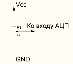
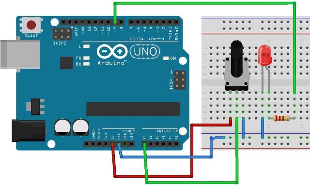
The circuit above allows you to read values from 0 to 1023, due to the fact that all the voltage drops on the potentiometer. Here the principle of the voltage divider works, in any position of the engine, the voltage is distributed linearly on the surface of the resistive layer or on a logarithmic scale (depends on the potentiometer) that part of the voltage that remains between the output of the slider (sliding contact) and ground (gnd) gets to the input. On the breadboard, this connection looks like this:
The second option is connected according to the classical resistive divider circuit, here the voltage at the point of maximum resistance of the potentiometer depends on the resistance of the upper resistor (in Figure R2).
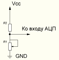
In general, the resistive divider is very important not only in the field of work with microcontrollers, but also in electronics in general. Below you see the general scheme, as well as the calculated ratios for determining the voltage value on the lower arm.
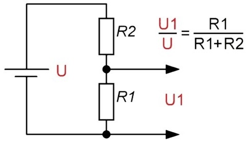
Such a connection is characteristic not only for a potentiometer, but for all analog sensors, because most of them work on the principle of changing resistance (conductivity) under the influence of external sources - temperature, light, radiation of various kinds, etc.
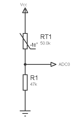
The following is the simplest connection diagram thermistor, in principle, a thermometer can be made on its basis. But the accuracy of its readings will depend on the accuracy of the table of conversion of resistance to temperature, the stability of the power source and the coefficients of change of resistance (including the upper arm resistor) under the same temperature. This can be minimized by selecting the optimal resistances, their power and operating currents.
In the same way, you can connect photodiodes, phototransistors as a light sensor. Photoelectronics has found application in sensors that determine the distance and the presence of an object, one of which we will consider later.
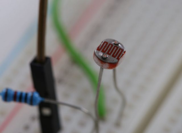
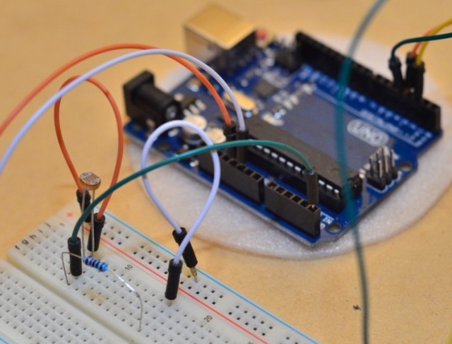
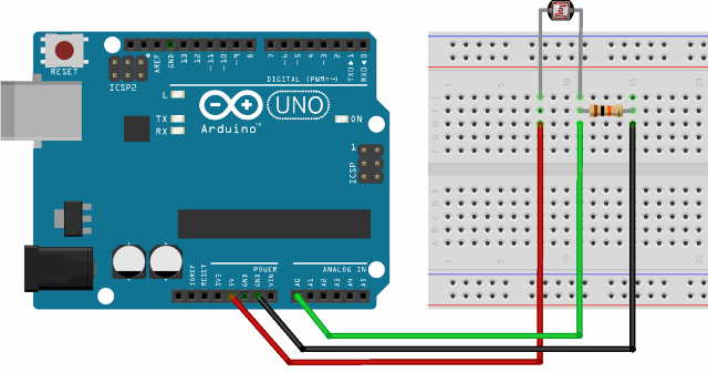
The figure shows the connection of the photoresistor to the arduino.
Software part
Before I talk about connecting specific sensors, I decided to consider software for processing them. All analog signals are read from the same ports using the analogRead () command.It is worth noting that Arduino UNO and other models with 168 and 328 atmega have 10-bit ADC. This means that the microcontroller sees the input signal as a number from 0 to 1023 - a total of 1024 values. If you consider that the supply voltage is 5 volts, then the input sensitivity:
5/1024 = 0.0048 V or 4.8 mV
That is, with a value of 0 at the input, the voltage is 0, and with a value of 10 at the input - 48 mV.
In some cases, to convert the values to the desired level (for example, to transmit to the PWM output), 1024 is divided by a number, and as a result of division, the required maximum should be obtained. The map function (source, low, high, high, high, low) works more clearly, where:
-
low - lower number before conversion by function;
-
vch - upper;
-
VCh - the lower number after processing by the function (at the output);
-
VHV - top.
A practical application for converting a function to an input value for transmission to a PWM (the maximum value is 255, for converting data from the ADC to the PWM output, 1024 is divided by 4):
Option 1 - division.
int x;
x = analogRead (pot) / 4;
// a number from 0 to 1023 will be received
// divide it by 4, we get an integer in from 0 to 255 analogWrite (led, x);
Option 2 - the MAP function - opens up more opportunities, but more on that later.
void loop ()
{int val = analogRead (0);
val = map (val, 0, 1023, 0, 255);
analogWrite (led, val); }
Or even shorter:
analogWrite (led, map (val, 0, 1023, 0, 255))
Not all sensors have 5 volts at the output, i.e. the number 1024 is not always convenient to divide to get the same 256 for the PWM (or any other). This can be 2 and 2.5 volts and other values, when the maximum signal will be, for example, 500.
Popular analog sensors
A general view of the sensor for arduino and its connection is shown below:
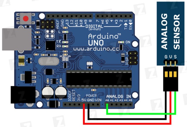
Usually there are three outputs, there may be a fourth - digital, but these are features.
Explanation of the designation of the outputs of the analog sensor:
-
G - minus power, common bus, ground. May be designated as GND, “-";
-
V - plus power. May be denoted as Vcc, Vtg, "+";
-
S - output signal, possible notation - Out, SGN, Vout, sign.
Beginners to learn how to read the values of sensors choose projects of all kinds of thermometers. Such sensors are in digital design, for example DS18B20, and in analog - these are all kinds of microcircuits like LM35, TMP35, TMP36 and others. Here is an example of the modular design of such a sensor on the board.
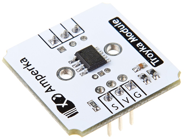
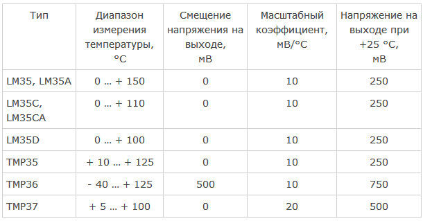
The accuracy of the sensor is from 0.5 to 2 degrees. Built on a TMP36 chip, like many of its analogs, its output values are 10 mV / ° C. At 0 °, the output signal is 0 V, and then 10 mV per 1 degree is added. That is, at 25.5 degrees, the voltage is 0.255 V, a deviation is possible within the error and self-heating of the IC crystal (up to 0.1 ° C).
Depending on the microcircuit used, the measurement ranges and output voltages may differ, see the table.
However, for a quality thermometer, you can’t just read the values and display them on the LCD indicator or serial port for communication with a PC, for the stability of the output signal of the whole system as a whole, you need to average the values from the sensors, both analog and digital, within certain limits, while without impairing their speed and accuracy (there is a limit to everything). This is due to the presence of noise, interference, unstable contacts (for resistive sensors based on a potentiometer, see malfunctions of the water or fuel level sensor in the car tank).
Codes for working with most sensors are quite voluminous, so I won’t give them all, they can be easily found on the network by the request “sensor + Arduino name”.
The next sensor that arduino robotic engineers often use is the line sensor. It is based on photoelectronic devices, type of phototransistors.
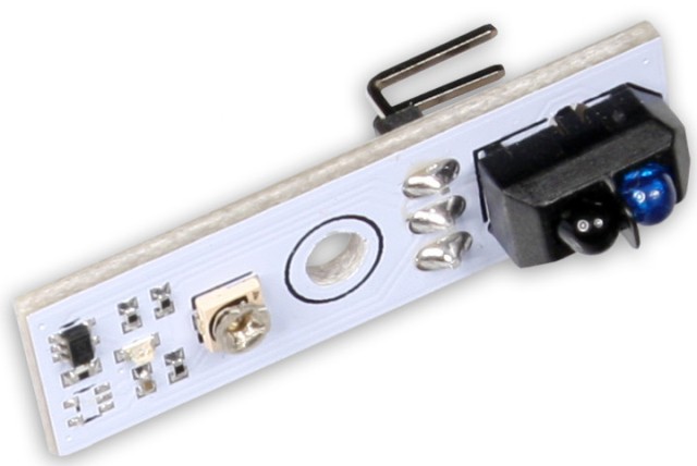
With their help, a robot that moves along the line (used in automated production to deliver parts) determines the presence of a white or black strip. On the right side of the figure, two devices similar to LEDs are visible. One of them is the LED, it can emit in the invisible spectrum, and the second is a phototransistor.
Light is reflected from the surface if it is dark - the phototransistor does not receive a reflected stream, but if the light receives and it opens. The algorithms that you put in the microcontroller process the signal and determine the correctness and direction of movement and correct them. The optical mouse, which you most likely hold in your hand while reading these lines, is similarly arranged.
I will supplement with an adjacent sensor - a distance sensor from Sharp, is also used in robotics, as well as in conditions of monitoring the position of objects in space (with the corresponding TX error).
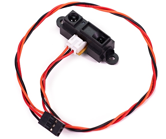
It works on the same principle. Libraries and examples of sketches and projects with them in large numbers are on sites dedicated to Arduino.
Conclusion
The use of analog sensors is very simple, and with the easy-to-learn Arduino programming language, you quickly learn simple devices. This approach has significant drawbacks in comparison with digital counterparts. This is due to the wide variation in parameters; this causes problems when replacing the sensor. You may have to edit the source code of the program.
True, individual analog devices incorporate reference voltage sources and current stabilizers, which has a positive effect on the final product and device repeatability in mass production. All problems can be avoided by using digital devices.
Digital circuitry as such reduces the need to tune and adjust the circuit after assembly. This gives you the opportunity to assemble several identical devices on the same source code, the details of which will give the same signals, with resistive sensors this is rare.
See also on our website:Connecting external devices to Arduino
See also at i.electricianexp.com
:
