Categories: Featured Articles » Practical Electronics
Number of views: 42091
Comments on the article: 0
How to use photoresistors, photodiodes and phototransistors
Sensors are completely different. They differ in principle of action, the logic of their work and the physical phenomena and quantities to which they are able to respond. Light sensors are not only used in automatic lighting control equipment, they are used in a huge number of devices, from power supplies to alarms and security systems.
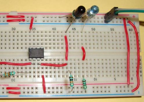
The main types of photoelectronic devices. General information
A photodetector in a general sense is an electronic device that responds to a change in the light flux incident on its sensitive part. They may differ, both in structure and in principle of operation. Let's look at them.
Photoresistors - change the resistance when lighting
A photoresistor is a photographic device that changes the conductivity (resistance) depending on the amount of light incident on its surface. The more intense illumination sensitive area, the less resistance. Here is a schematic of it.
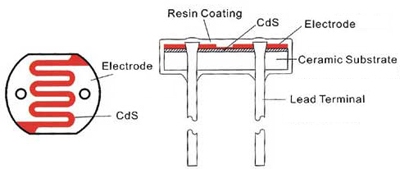
It consists of two metal electrodes, between which there is a semiconductor material. When the light flux hits the semiconductor, charge carriers are released in it, this contributes to the passage of current between the metal electrodes.

The energy of the light flux is spent on overcoming the band gap by the electrons and their transition into the conduction band. As a semiconductor, photoconductors use materials such as: Cadmium Sulfide, Lead Sulfide, Cadmium Selenite and others. The spectral characteristic of the photoresistor depends on the type of this material.
Interesting:
The spectral characteristic contains information about which wavelengths (color) of the light flux are most sensitive to a photoresistor. For some instances, it is necessary to carefully select a light emitter of the appropriate wavelength, in order to achieve the greatest sensitivity and work efficiency.
The photoresistor is not designed to accurately measure illumination, but rather to determine the presence of light, according to its readings, the environment can be detected lighter or darker. The current-voltage characteristic of the photoresistor is as follows.
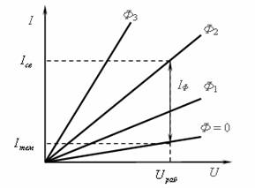
It depicts the dependence of current on voltage for various values of the light flux: Ф - darkness, and Ф3 - this is bright light. It is linear. Another important characteristic is sensitivity, it is measured in mA (μA) / (Lm * V). This reflects how much current flows through the resistor, with a certain luminous flux and an applied voltage.
Dark resistance is the active resistance in the complete absence of illumination, it is denoted by RT, and the characteristic RT / Rb is the rate of change in resistance from the state of the photoresistor in the complete absence of lighting to the maximum illuminated state and the minimum possible resistance, respectively.
Photoresistors have a significant drawback - its cutoff frequency. This value describes the maximum frequency of the sinusoidal signal with which you model the luminous flux, at which the sensitivity decreases by 1.41 times. In reference books, this is reflected either by the frequency value, or through a time constant. It reflects the speed of devices, which usually takes tens of microseconds - 10 ^ (- 5) s. This does not allow you to use it where you need high performance.
Photodiode - converts light into electrical charge
A photodiode is an element that converts light entering a sensitive area into an electric charge. This is because various processes associated with the movement of charge carriers occur during irradiation in the pn junction.
If the conductivity changed on the photoresistor due to the motion of charge carriers in the semiconductor, then a charge is formed at the boundary of the pn junction. It can operate in the mode of a photoconverter and a photo generator.

In structure, it is the same as a conventional diode, but on its case there is a window for the passage of light. Outwardly, they come in various designs.
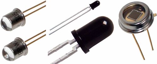
Black body photodiodes only accept infrared radiation. Black coating is something like tinting. Filters the IR spectrum to exclude the possibility of triggering the radiation of other spectra.
Photodiodes, like photoresistors, have a cutoff frequency, only here it is orders of magnitude larger and reaches 10 MHz, which allows for good performance. P-i-N photodiodes have a high speed - 100 MHz-1 GHz, like diodes based on the Schottky barrier. Avalanche diodes have a cutoff frequency of about 1-10 GHz.
In photoconverter mode, such a diode works like a key controlled by light, for this it is connected to the circuit in forward bias. That is, the cathode to a point with a more positive potential (to plus), and the anode to a more negative potential (to minus).
When the diode is not illuminated by light, only the reverse dark current Iobrt flows (units and tens of μA), and when the diode is lit, a photocurrent is added to it, which depends only on the degree of illumination (tens of mA). The more light, the more current.
Photocurrent If equals:
Iph = Sint * F,
where Sint is the integral sensitivity, Ф is the luminous flux.
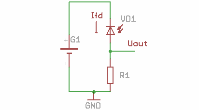
A typical scheme for switching on a photodiode in photoconverter mode. Pay attention to how it is connected - in the opposite direction with respect to the power source.
Another mode is the generator. When light enters the photodiode, voltage is generated at its terminals, while the short-circuit currents in this mode are tens of amperes. It reminds operation of solar cellsbut have low power.
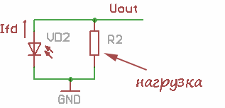
Phototransistors - open by the amount of incident light
Phototransistor is inherently bipolar transistor which instead of the base output has a window in the case for light to enter there. The principle of operation and the reasons for this effect are similar to previous devices. Bipolar transistors are controlled by the amount of current flowing through the base, and phototransistors, by analogy, are controlled by the amount of light.
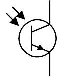
Sometimes UGO still additionally depicts the output of the base. In general, the voltage is supplied to the phototransistor as well as to the usual one, and the second option is switched on with a floating base, when the basic output remains unused.
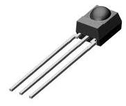
Phototransistors are likewise included in the circuit.
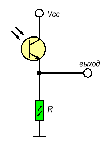
Or swap the transistor and resistor, depending on what exactly you need. In the absence of light, a dark current flows through the transistor, which is formed from the base current, which you can set yourself.
By setting the required base current, you can set the sensitivity of the phototransistor by selecting its base resistor. In this way, even the faintest light can be captured.
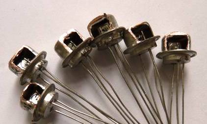
In Soviet times, radio amateurs made phototransistors with their own hands - they made a window for light, cutting off part of the case with a conventional transistor. For this, transistors like MP14-MP42 are excellent.
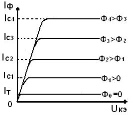
From the current-voltage characteristic, the dependence of the photocurrent on lighting is visible, while it is practically independent of the collector-emitter voltage.
In addition to bipolar phototransistors, there are field ones. Bipolar ones operate at frequencies of 10-100 kHz, then field ones are more sensitive. Their sensitivity reaches several amperes per lumen, and more “fast” - up to 100 MHz. Field-effect transistors have an interesting feature: at maximum values of the luminous flux, the gate voltage almost does not affect the drain current.
Scopes of photoelectronic devices
First of all, you should consider more familiar options for their application, for example, automatic inclusion of light.
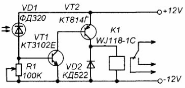
The diagram shown above is the simplest device for turning on and off the load in a certain light condition. Photodiode FD320 When light enters it, a certain voltage opens and R1 drops a certain voltage when its value is sufficient to open the transistor VT1 - it opens and opens another transistor - VT2. These two transistors are a two-stage current amplifier, necessary to power the relay coil K1.
Diode VD2 - needed to suppress the EMF self-induction, which is formed when switching the coil. One of the wires from the load is connected to the relay input terminal, the top one according to the scheme (for alternating current - phase or zero).
We have normally closed and open contacts, they are needed either to select the circuit to be switched on, or to select to turn on or off the load from the network when the required light is reached. Potentiometer R1 is needed to adjust the device to operate at the right amount of light. The greater the resistance, the less light is needed to turn on the circuit.
Variations of this scheme are used in most similar devices, adding a certain set of functions if necessary.
In addition to switching on the light load, such photodetectors are used in various control systems, for example, photoresistors are often used on metro turnstiles to detect unauthorized (hare) crossing of the turnstile.
In a printing house, when a strip of paper breaks, light enters the photodetector and thereby gives the operator a signal about this. The emitter is on one side of the paper, and the photodetector is on the back. When the paper is torn, the light from the emitter reaches the photodetector.
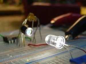
In some types of alarms, an emitter and a photodetector are used as sensors for entering the room, and infrared devices are used so that the radiation is not visible.
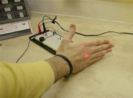
Regarding the IR spectrum, you can not mention the TV receiver, which receives signals from the IR LED in the remote control when you switch channels. Information is encoded in a special way and the TV understands what you need.
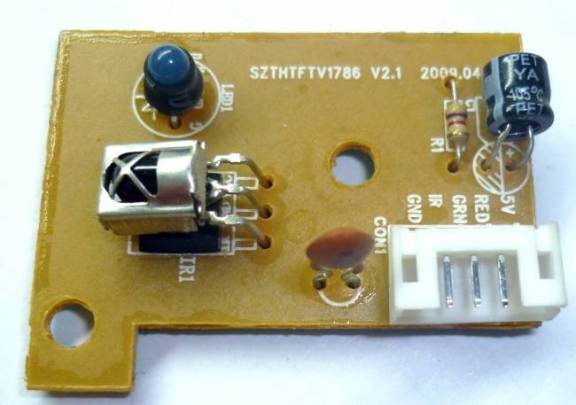
Information thus previously transmitted through the infrared ports of mobile phones. The transmission speed is limited both by the sequential transmission method and the principle of operation of the device itself.
Computer mice also use technology associated with photoelectronic devices.
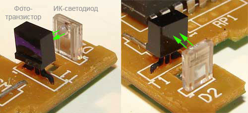
Application for signal transmission in electronic circuits
Optoelectronic devices are devices that combine a transmitter and a photodetector in the same housing, such as those described above. They are needed to connect two circuits of the electric circuit.
This is necessary for galvanic isolation, fast signal transmission, as well as for connecting DC and AC circuits, as in the case of triac control in a 220 V 5 V circuit with a signal from the microcontroller.
They have a graphic designation that contains information about the type of elements used inside the optocoupler.
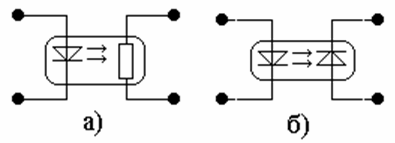
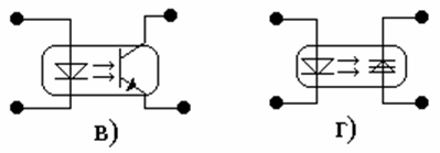
Consider a couple of examples of the use of such devices.
Controlling a triac using a microcontroller
If you are designing a thyristor or triac converter, you will run into a problem. Firstly, if the transition at the control output breaks through - to the pin of the microcontroller high potential will fall and the latter will fail. For this, special drivers have been developed, with an element called an optosymistor, for example, MOC3041.
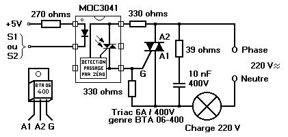
Optocouple Feedback
In stabilized switching power supplies, feedback is required. If we exclude galvanic isolation in this circuit, then in case of failure of some components in the OS circuit, high potential will appear on the output circuit and the connected equipment will fail, I'm not talking about the fact that you can be shocked.
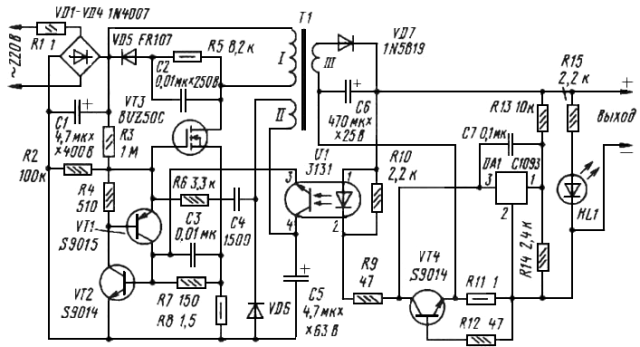
In a specific example, you see the implementation of such an OS from the output circuit to the feedback winding (control) of the transistor using an optocoupler with the serial designation U1.
conclusions
Photo and optoelectronics are very important sections in electronics, which have significantly improved the quality of the equipment, its cost and reliability. Using an optocoupler, it is possible to exclude the use of an isolation transformer in such circuits, which reduces the overall dimensions. In addition, some devices are simply impossible to implement without such elements.
See also at i.electricianexp.com
:
