Categories: Featured Articles » Practical Electronics
Number of views: 127164
Comments on the article: 5
Photosensors and their application
What are photosensors
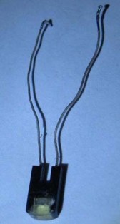
 In various electronic devices, home and industrial automation devices, various amateur radio designs photosensors are used very widely. Anyone who has ever disassembled an old computer mouse, as it was called a “komovskaya,” with a ball inside, must have seen wheels with slots spinning in the slots of the photosensors.
These photosensors are called photo interrupters - interrupt the flow of light. On one side of such a sensor is a source - Light-emitting diodeas a rule, infrared (IR), with another phototransistor (to be more precise, two phototransistors, in some models of the photodiode, to determine also the direction of rotation). When the wheel is rotated with slots at the output of the photosensor, electrical impulses are obtained, which is information about the angular position of this wheel itself. Such devices are called encoders. Moreover, the encoder can be just a contact, remember the wheel of a modern mouse!
Photo interrupters are used not only in “mice” but also in other devices, for example, speed sensors of some mechanism. In this case, a single photosensor is used, because the direction of rotation is not required to be determined.
If for some reason, most often for repair, climb into other electronic devices, then photo sensors can be found in printers, scanners and copiers, in CD drives, in DVD players, video cassette recorders, camcorders and other equipment.
So what are photosensors, and what are they? Just see, without going into the physics of semiconductors, not understanding the formulas and not uttering incomprehensible words (recombination, resorption of minority carriers), which is called “on the fingers”, how these photosensors work.
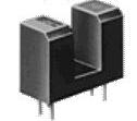
Figure 1. Photo Interrupter
Photoresistor
Everything is clear with him. As an ordinary constant resistor has an ohmic resistance, the direction of connection in the circuit does not play a role. Only unlike a constant resistor, it changes the resistance under the influence of light: when illuminated, it decreases several times. The number of these “times” depends on the model of the photoresistor, primarily on its dark resistance.
Structurally, the photoresistors are a metal case with a glass window through which a grayish-colored plate with a zigzag track is visible. Later models were carried out in a plastic case with a transparent top.
The speed of photoresistors is low, so they can work only at very low frequencies. Therefore, in new developments, they are almost never used. But it happens that in the process of repairing old equipment they will have to meet.
To check the health of the photoresistor, it is enough to check its resistance with a multimeter. In the absence of lighting, the resistance should be large, for example, the photoresistor SF3-1 has a dark resistance according to the reference data of 30MOhm. If it is lit, then the resistance will drop to a few KOhms. The appearance of the photoresistor is shown in Figure 2.
Figure 2. Photoresistor SF3-1
Photodiodes
Very similar to a conventional rectifier diode, if not for the property of reacting to light. If you “ring” it with a tester, it is better to use an up-to-date switch, then in the absence of lighting the results will be the same as in the case of a conventional diode: in the forward direction the device will show a little resistance, and in the opposite direction the device’s arrow will hardly move.
They say that the diode is turned on in the opposite direction (this point should be remembered), so the current does not flow through it. But, if in this inclusion the photodiode is lit with a light bulb, then the arrow will abruptly rush to the zero mark.This mode of operation of the photodiode is called photodiode.
The photodiode also has a photovoltaic mode of operation: when light hits it, it, like solar battery, produces a weak voltage, which, if strengthened, can be used as a useful signal. But, more often the photodiode is used in photodiode mode.
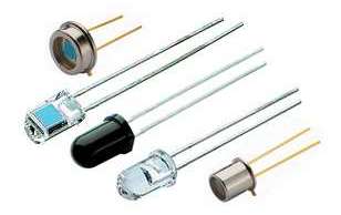
The photodiodes of the old design in appearance are a metal cylinder with two leads. On the other hand is a glass lens. Modern photodiodes have a housing made of transparent plastic, exactly the same as LEDs.
Fig. 2. Photodiodes
Phototransistors
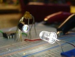
In appearance, they are simply indistinguishable from LEDs, the same case is made of transparent plastic or a cylinder with a glass in the end, and from it there are two outputs - a collector and an emitter. The phototransistor does not seem to need a basic output, because the input signal for it is the light flux.
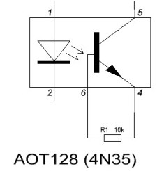
Although, some phototransistors still have a base output, which, in addition to light, also allows the transistor to be controlled electrically. This can be found in some transistor optocouplers, for example, AOT128 and imported 4N35, which are essentially functional analogs. A resistor is connected between the base and the emitter of the phototransistor to slightly cover the phototransistor, as shown in Figure 4.
Figure 3. Phototransistor
Our optocoupler usually "hangs" 10-100KΩ, while the imported "analog" has about 1MΩ. If you put even 100K, it will not work, the transistor is just tightly closed.
How to check a phototransistor
A phototransistor can simply be checked by a tester, even if it does not have a base output. When an ohmmeter is connected in any polarity, the resistance of the collector - emitter section is quite large, since the transistor is closed. When light of sufficient intensity and spectrum gets on the lens, the ohmmeter will show a little resistance - the transistor opened, if, of course, it was possible to guess the polarity of the tester connection. In fact, this behavior resembles a conventional transistor, only it opens with an electric signal, and this one with a light stream. In addition to the intensity of the light flux, its spectral composition plays an important role. For transistor test features, see here.
Light spectrum
Typically, photosensors are tuned to a specific wavelength of light radiation. If this is infrared radiation, then such a sensor does not respond well to blue and green LEDs, good enough to red, an incandescent lamp, and of course to infrared. It also does not accept light from fluorescent lamps. Therefore, the reason for the poor operation of the photosensor may simply be an inappropriate spectrum of the light source.
It was written above how to ring a photodiode and a phototransistor. Here you should pay attention to such a seemingly trifle as the type of measuring device. In a modern digital multimeter, in the mode of semiconductor continuity, plus is in the same place as when measuring DC voltage, i.e. on the red wire.
The result of the measurement will be the voltage drop in millivolts at the p-n junction in the forward direction. As a rule, these are numbers in the range of 500 - 600, which depends not only on the type of semiconductor device, but also on temperature. With increasing temperature, this figure decreases by 2 for every degree Celsius, which is due to the temperature coefficient of resistance of the TCS.
When using a pointer tester, it must be remembered that in the resistance measurement mode, the positive output is on the minus in the voltage measurement mode. With such checks, it is better to illuminate the photo sensors with an incandescent lamp at close range.
Pairing the photosensor with a microcontroller
Recently, many radio enthusiasts have taken a great interest in designing robots. Most often this is something that seems primitive, like a box with batteries on wheels, but terribly smart: hears everything, sees everything, and goes around obstacles.He sees everything just due to phototransistors or photodiodes, and maybe even photoresistors.
Everything is very simple here. If this is a photoresistor, it is enough to connect it, as indicated in the diagram, and in the case of a phototransistor or photodiode, so as not to confuse the polarity, “ring” them first, as described above. It is especially useful to do this operation, if the parts are not new, make sure that they are suitable. Connecting different photo sensors to microcontroller shown in figure 4.
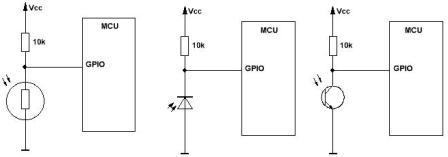
Figure 4. Schemes for connecting photosensors to a microcontroller
Light measurement
Photodiodes and phototransistors have low sensitivity, high non-linearity and a very narrow spectrum. The main application of these photo devices is to work in key mode: on - off. Therefore, the creation of light meters on them is quite problematic, although earlier in all analog light meters they were used precisely these photosensors.
But fortunately, nanotechnology does not stand still, but goes forward by leaps and bounds. To measure the illumination "there they have" created a specialized chip TSL230R, which is a programmable converter of illumination - frequency.
Externally, the device is a chip in a DIP8 case made of transparent plastic. All input and output signals in level are compatible with TTL - CMOS logic, which makes it easy to pair the converter with any microcontroller.
Using external signals, you can change the sensitivity of the photodiode and the scale of the output signal, respectively, 1, 10, 100 and 2, 10, and 100 times. The dependence of the frequency of the output signal on the illumination is linear, ranging from fractions of a hertz to 1 MHz. Scale and sensitivity settings are performed by supplying logic levels to just 4 inputs.
The microcircuit can be introduced into micro consumption mode (5 μA) for which there is a separate conclusion, although it is not particularly voracious in the operating mode. With a supply voltage of 2.7 ... 5.5 V, the current consumption is not more than 2 mA. For the operation of the chip does not require any external strapping, except that the blocking capacitor for power.
In fact, it’s enough to connect a frequency meter to the microcircuit and get illumination readings, well, apparently, in some UEs. In the case of using the microcontroller, focusing on the frequency of the output signal, you can control the illumination in the room, or simply by the principle of "turn on - off".
TSL230R is not the only light meter. Even more advanced are Maxim MAX44007-MAX44009 sensors. Their dimensions are smaller than that of the TSL230R, the power consumption is the same as that of other sensors in sleep mode. The main purpose of such light sensors is the use in battery powered devices.
Photosensors control lighting
One of the tasks performed with the help of photosensors is lighting control. Such schemes are called photo relay, most often this is a simple inclusion of lighting in the dark. To this end, many amateurs have developed many circuits, some of which we will consider in the next article.
Continuation of the article: Photo relay schemes for lighting control
See also at bgv.electricianexp.com
:

