Categories: Featured Articles » Practical Electronics
Number of views: 53054
Comments on the article: 0
How to choose an analog transistor
 In this article, we will discuss the topic of selecting analogues of bipolar and field effect transistors. What parameters of the transistor should you pay attention to in order to choose the appropriate replacement?
What is it for? It happens that when repairing a device, say, a switching power supply, the user is forced to contact the nearest store of electronic components, but the assortment does not contain just such a transistor that failed in the device circuit. Then you have to choose from what is available, that is, select an analogue.
And it also happens that the burned-out transistor on the board was one of those that have already been discontinued, and then it’s just the right thing to do is the datasheet available on the network, where you can see the parameters and select the appropriate analogue from those currently available. One way or another, you need to know what parameters to choose, and this will be discussed later.
Bipolar transistors

To start, let's talk about bipolar transistors. The main characteristics here are:
-
maximum collector-emitter voltage
-
maximum collector current
-
maximum power dissipated by the transistor case,
-
cutoff frequency
-
current transfer coefficient.
First of all, they evaluate the scheme as a whole. At what frequency does the device work? How fast should the transistor be? It is best if the operating frequency of the device is 10 or many times lower than the cutoff frequency of the transistor. For example, fg is 30 MHz, and the operating frequency of the device where the transistor will operate is 50 kHz.
If you make the transistor work at a frequency close to the boundary, then the current transfer coefficient will tend to unity, and a lot of energy will be required for control. Therefore, let the boundary frequency of the selected analog be greater than or equal to the boundary frequency of the transistor that needs to be replaced.
The following steps pay attention to the power that the transistor can dissipate. Here they look at the maximum collector current and at the limit value of the collector-emitter voltage. The maximum collector current must be higher than the maximum current in the transistor controlled circuit. The maximum collector-emitter voltage of the selected transistor must be higher than the limit voltage in the controlled circuit.
If the parameters are selected based on the datasheet for the component to be replaced, then the selected analog in terms of voltage limit and current limit should match or exceed the replaceable transistor. For example, if a transistor burns down, the maximum collector-emitter voltage of which is 80 volts, and the maximum current is 10 amperes, then in this case, an analog with maximum parameters for current and voltage of 15 amperes and 230 volts is suitable as a replacement.

Next, the current transfer coefficient h21 is estimated. This parameter indicates how many times the collector current exceeds the base current in the process of controlling the transistor. It is better to give priority to transistors with a value of this parameter greater than or equal to h21 of the original component, at least approximately.
You can’t replace the transistor with h21 = 30, the transistor with h21 = 3, the control circuit simply can’t cope or burn out, and the device cannot work normally, it is better if the analog has h21 at the level of 30 or more, for example 50. The higher the gain current, the easier it is to control the transistor, the higher the control efficiency, the base current is less, the collector current is more.
The transistor enters saturation without unnecessary costs. If the device where the transistor is selected has an increased requirement for the current transfer coefficient, then the user should choose an analog with a closer to the original h21, or you will have to make changes to the base control circuit.
Finally, look at the saturation voltage, collector-emitter voltage of an open transistor. The smaller it is, the less power will be dissipated on the component case in the form of heat.And it’s important to note how much the transistor will actually have to dissipate heat in the circuit, the maximum value of the power dissipated by the housing is given in the documentation (in the datasheet).
Multiply the collector circuit current by the voltage that will fall at the collector-emitter junction during the operation of the circuit, and compare with the maximum thermal power allowed for the transistor case. If the actually allocated power is greater than the limit, the transistor will quickly burn out.
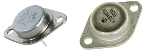
So, the bipolar transistor 2N3055 can be safely replaced with KT819GM and vice versa. Comparing their documentation, we can conclude that these are almost complete analogs, both in structure (both NPN) and in case type and in basic parameters, which are important for equally effective operation in similar modes.
Field effect transistors

Now let's talk about field effect transistors. Field effect transistors are widely used today, in some devices, for example in inverters, they almost completely replaced bipolar transistors. Field-effect transistors are controlled by voltage, the electric field of the gate charge, and therefore the control is less expensive than in bipolar transistors, where the base current is controlled.
Field effect transistors switch much faster compared to bipolar ones, have increased thermal stability, and do not have minority charge carriers. To ensure switching of significant currents, field-effect transistors can be connected in parallel in large numbers without leveling resistors, it is enough to choose the appropriate driver.
So, with regard to the selection of analogs of field-effect transistors, the algorithm here is the same as with the selection of bipolar analogs, with the only difference being that there is no problem with the current transfer coefficient and an additional parameter such as the gate capacitance appears. Maximum drain-source voltage, maximum drain current. It is better to choose with a margin so that it probably does not burn out.
Field-effect transistors do not have such a parameter as saturation voltage, but there is a parameter “channel resistance in the open state”. Based on this parameter, you can determine how much power will be dissipated on the component case. Open channel resistance can range from fractions of an ohm to units of an ohm.
In high-voltage field-effect transistors, the open channel resistance is usually more than one ohm, and this must be taken into account. If it is possible to choose an analog with a lower open channel resistance, then there will be less heat loss, and the voltage drop at the junction will not be critically high in the open state.
The steepness of the S characteristic of field-effect transistors is an analog of the current transfer coefficient of bipolar transistors. This parameter shows the dependence of the drain current on the gate voltage. The higher the slope of the S characteristic, the less voltage must be applied to the gate to switch a significant drain current.
Do not forget about the threshold voltage of the gate when choosing an analogue, because if the voltage on the gate is lower than the threshold, the transistor will not fully open and the switched circuit will not receive enough power, all the power will have to be dissipated by the transistor, and it will simply overheat. The gate control voltage must be higher than the threshold voltage. An analog should have a threshold gate voltage not higher than the original.
The dissipation power of a field-effect transistor is similar to the dissipation power of a bipolar transistor, this parameter is indicated in the datasheet, and, as in the case of bipolar transistors, depends on the type of housing. The larger the component housing, the greater the thermal power it can dissipate for itself safely.
Shutter capacity. Since field-effect transistors are controlled by the gate voltage, and not by the base current, like bipolar transistors, such a parameter as the gate capacitance and the total gate charge are introduced here.When choosing an analog to replace the original, pay attention to the fact that the shutter of the analog is not heavier.
The shutter capacity is best if it turns out to be slightly less, it is easier to control such a field-effect transistor, the edges will turn out steeper. However, if you do not intend to solder the gate resistors in the control circuit, then let the gate capacitance be as close as possible to the original.
So, very common a few years ago, the IRFP460 is replaced with a 20N50, which has a slightly lighter shutter. If we turn to datasheets, it is easy to notice the almost complete similarity of the parameters of these field effect transistors.
We hope that this article helped you figure out what characteristics you need to focus on in order to find the suitable analog of the transistor.
See also at bgv.electricianexp.com
:
