Categories: Microcontroller circuits
Number of views: 9996
Comments on the article: 0
Measuring temperature and humidity on Arduino - a selection of ways
To create a home weather station or thermometer, you need to learn how to pair the Arduino board and a device for measuring temperature and humidity. Temperature measurement can be dealt with using a thermistor or a digital sensor DS18B20, but for measuring humidity use more complex devices - sensors DHT11 or DHT22. In this article, we’ll show you how to measure temperature and humidity using the Arduino and these sensors.

Thermistor Measurement
The easiest way to determine the temperature is to use thermistor. This is a type of resistor whose resistance depends on the ambient temperature. There are thermistors with a positive and negative temperature coefficient of resistance - PTC (also called posistors) and NTC-thermistors, respectively.
In the graph below you see the temperature dependence of resistance. The dashed line shows the dependence for a negative TCS thermistor (NTC), and the solid line for a positive TCS thermistor (PTC).

What do we see here? The first thing that catches your eye is that the schedule for the PTC thermistor is broken and it will be difficult or impossible to measure a number of temperature values, but the schedule for the NTC thermistor is more or less uniform, although it is clearly non-linear. What does it mean? Using an NTC thermistor is easier to measure temperature, because it is easier to find out the function by which its values change.
To convert the temperature to resistance, you can manually take the values, but this is difficult to do at home and you need a thermometer to determine the real values of the temperature of the medium. In the datasheets of some components, such a table is given, for example, for a series of NTC thermistors from Vishay.

Then you can organize the translation through the branches using the function if ... else or switchcase. However, if there are no such tables in the datasheets, you have to calculate the function by which the resistance changes with increasing temperature.
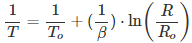
To describe this change, the Steinhart-Hart equation exists.

where A, B and C are the thermistor constants determined by measuring three temperatures with a difference of at least 10 degrees Celsius. At the same time, different sources indicate that for a typical 10 kΩ NTC thermistor they are equal to:

B - beta coefficient, it is calculated based on the measurement of resistance for two different temperatures. It is indicated either in the datasheet (as illustrated below), or calculated independently.

In this case, B is indicated in the form:

This means that the coefficient was calculated based on the data obtained when measuring resistance at temperatures of 25 and 100 degrees Celsius, and this is the most common option. Then it is calculated by the formula:
B = (ln (R1) - ln (R2)) / (1 / T1 - 1 / T2)
A typical connection diagram of a thermistor to a microcontroller is shown below.

Here R1 is a constant resistor, the thermistor is connected to the power source, and the data is taken from the midpoint between them, the diagram conditionally indicates that the signal is supplied to pin A0 - this analog input Arduino.

To calculate the resistance of a thermistor, you can use the following formula:
R of thermistor = R1⋅ ((Vcc / Voutput) −1)
To translate into a language that is understandable for arduino, you need to remember that the arduino has a 10-bit ADC, so the maximum digital value of the input signal (voltage 5V) will be 1023. Then, conditionally:
-
Dmax = 1023;
-
D is the actual value of the signal.
Then:
R of thermistor = R1⋅ ((Dmax / D) −1)
Now we use this to calculate the resistance and then calculate the temperature of the thermistor using the beta equation in a programming language for Arduino. The sketch will be like this:

DS18B20
Even more popular for measuring temperature with.Arduino found a digital sensor DS18B20. It communicates with the microcontroller via the 1-wire interface, you can connect several sensors (up to 127) to one wire, and to access them you will need to find out the ID of each of the sensors.
Note: you should know the ID even if you use only 1 sensor.

The connection diagram of the ds18b20 sensor to Arduino looks like this:


There is also a parasitic power mode - its connection diagram looks like this (you need two wires instead of three):

In this mode, correct operation is not guaranteed when measuring temperatures above 100 degrees Celsius.
The DS18B20 digital temperature sensor consists of a whole set of nodes, like any other SIMS. You can watch its internal device below:

To work with it, you need to download the Onewire library for Arduino, and for the sensor itself it is recommended to use the DallasTemperature library.

This code example demonstrates the basics of working with 1 temperature sensor, the result in degrees Celsius is output through the serial port after each read.
DHT11 and DHT22 - humidity and temperature sensors

These sensors are popular and often used to measure humidity and ambient temperature. In the table below we indicated their main differences.

The connection diagram is quite simple:
-
1 conclusion - nutrition;
-
2 conclusion - data;
-
3 conclusion - not used;
-
4 conclusion - the general wire.
If your sensor is made in the form of a module, it will have three outputs, but no resistor is needed - it is already soldered to the board.

To work, we need the dht.h library, it is not in the standard set, so it needs to be downloaded and installed in the libraries folder in the folder with the arduino IDE. It supports all sensors in this family:
-
DHT 11;
-
DHT 21 (AM2301);
-
DHT 22 (AM2302, AM2321).
Example library usage:

Conclusion
Nowadays, creating your own station for measuring temperature and humidity is very simple thanks to the Arduino platform. The cost of such projects is 3-4 hundred rubles. For battery life, and not output to a computer, can be used character display (we described them in a recent article), then you can build a portable device for use both at home and in the car. Write in the comments what else you would like to learn about simple homemade crafts on arduino!
See also on this topic:Popular sensors for Arduino - connection, diagrams, sketches
See also at i.electricianexp.com
: