Categories: Microcontroller circuits
Number of views: 13565
Comments on the article: 0
Features connecting devices to Arduino
Platform for robotics and automation lovers Arduino famous for its modular design and ease of use. Sometimes I come across an advertisement where they say that you can assemble your robot without practically being familiar with electronics. But it is not so.
If some actuators and mechanisms are connected incorrectly, you can burn arduinka ports (as I already described in the article about how not to burn Arduino) And if you do not know how to handle digital devices - at best you simply will not be able to establish a connection.
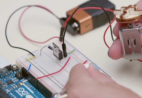
I bought several modules for arduino, what to do next?
To learn about the features of the connection, power supply voltages, logic levels, etc. you need to familiarize yourself with the datasheet on your module.
Datasheet or datasheet is the technical documentation for the product. Such documentation can be downloaded to any chip or sensor. Usually they are on the manufacturer’s website. Moreover, there are special resources on the network, on which a whole mass of technical documentation is collected
Read the information from the datasheet carefully, but what should I look for? Firstly, a chip, in addition to the main part of the name, usually has a variable part or prefix - most often it is one or more letters.
This indicates some features of a particular microcircuit, for example, maximum power, supply voltages and logical levels (if the device is digital), possibly the case in which it is executed, etc.
If you did not find nutrition information and a log in the datasheet. levels, contact the Russian-speaking community of arduino, on their forums the features of all common modules are usually considered.
ArduinoUno has a supply voltage and logic levels of 5 V, if the external device operates in the 3.3 V range, you will have to form them, you can arrange power using an LDO stabilizer (linear with a low drop, to stabilize it needs at least 1.3 volts of “excess voltage at maximum current, against 2 volts on the stabilizers of the 78xx series, which allows you to get 3.3 volts from 4.5 volts (three finger batteries).
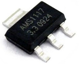
The technical documentation for digital sensors and devices also indicates the names of the protocols by which they "communicate" with each other. These can be individual protocols and standard, the same:
-
UART
-
I2C;
-
SPI
Arduino works with them. This will make it easier for you to find ready-made libraries and code samples.
Signal conditioning and amplification
Questions about matching devices and actuators with arduino quite often arise among beginners. We will consider common ones:
1. Matching voltage circuits.
2. The coordination of the power of the output pin and actuator, in other words, the amplification of voltage and / or current.
Level Matching
What should I do if the logic levels on my module are 3.3 Volts, and on the arduino 5 Volts? It is quite simple to use a logic level converter. It can be assembled from discrete elements, or you can purchase a ready-made module on the board, for example this:
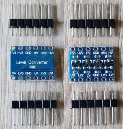
Such a converter is bidirectional, i.e. it lowers the high level and increases the response low. LV (1,2,3,4) - platforms for connecting low-level signals, HV (1,2,3,4) - high levels, HV and LV without numbers - these are voltages of 5 and 3.3 Volts, as with sources of converted signals GND - ground or negative wire. In a particular instance there are 4 independent channels.
Circuit matching with large voltage differences
If you are going to start a signal, for example from high-voltage circuits, for example 220 V, you need to use an optocoupler.This will provide galvanic isolation and protection against high-voltage bursts of the inputs of the microcontroller. Such circuits are used both for receiving a signal and for output signals from a microcontroller to a network, as well as to control triacs in chains.
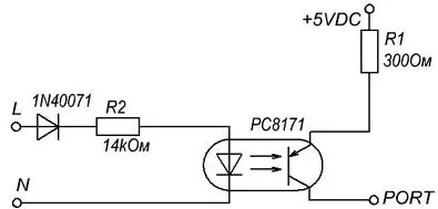
The probability of the appearance of a high potential on the arduino board in this case is extremely small, this is ensured by the absence of electrical contact, and communication is via an optical channel, i.e. with the help of light. You can learn more about this by studying photo- and optoelectronic devices.
If a big leap occurs, the optocoupler will burn, the picture is PC8171, but you will not overload the ports of the microcontroller.
Connecting Powerful Consumers
Since the microcontroller can only control the operation of devices, you cannot connect a powerful consumer to its port. Examples of such consumers:
-
Relay;
-
Solenoids;
-
Electric motors;
-
Servos.
1. Servo connection
The main task of the servo drive is to set the position of the rotor connected to the actuators, to control and change it using small efforts. That is, you, with the help of a potentiometer, if the servo drive is designed to rotate within half a revolution (180 degrees) or with the help of an encoder, if circular rotation (360 degrees) is needed, you can control the position of the servo shaft (electric motor in our case) of arbitrary power.
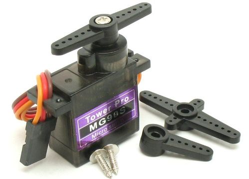
Many robotics enthusiasts use arduino as the basis of their robots. Here servos have found great use. They are used as a drive of rotary mechanisms for cameras, sensors and mechanical hands. Radio modelers use to drive turning wheels in car models. The industry uses large drives in CNC machines and other automation.
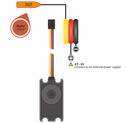
In amateur small services, a board with a position sensor and electronics is integrated in the case. Three wires usually come out of them:
-
Red - plus power, if a powerful drive is better connected to an external source, and not to the Arduino board;
-
Black or brown - minus, the connection as well as plus;
-
Yellow or orange - the control signal - it is fed from the digital pin of the microcontroller (digital out).
A special library is provided for managing the server, access to it is declared at the beginning of the code with the command "#include servo.h".
Motor connection
To drive mechanisms and adjust their rotation speed, it is easiest to use DPT (a brush DC motor with excitation from permanent magnets). You probably saw such motors in radio-controlled cars. They are easily reversed (turned on to rotate in the right direction) you just need to change the polarity. Do not try to connect them to the pins directly!
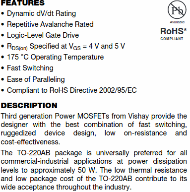
Better use a transistor. Will fit any bipolar, at least direct (pnp), at least reverse (npn) conductivity. Field works, too, but when choosing a specific one, make sure that its shutter works with logical levels?
Otherwise, it will not open completely, or you will burn the digital output of the microcontroller while charging the gate capacitance - they use a driver, the simplest way is to pump the signal through a bipolar transistor. Below is the control circuit through field-effect transistor.
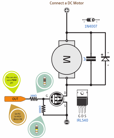
If there is no resistor between G and S, then the shutter (G) will not be pulled to the ground and may spontaneously “walk” from interference.
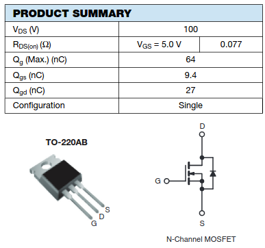
How to determine that a field effect transistor is suitable for direct control from a microcontroller, see below. In the datasheet, find the Vgs parameter, for example, for IRL540 all measurements and graphs are tied to Vgs = 5v, even such a parameter as the open channel resistance is indicated for this voltage between the gate and the source.
In addition to the brush DPT, the cooler can be connected from the computer in the same way, although there is a brushless motor, the windings of which are controlled by the built-in converter, the board of which is located directly in its case.
The revs of these two types of motors are easy to adjust by varying the supply voltage. This can be done if the transistor base is connected not in digital (digital output), but with a pin (~ pwm), the value of which is determined by the function "analogWrite ()".
Relays and Solenoids
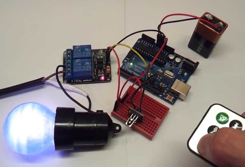
For switching circuits where regulation is not necessary and frequent switching is convenient to use a relay. By choosing the right one, you can switch any currents and voltages with minimal losses in conductivity and heating of power lines.
To do this, apply the voltage required to the relay coil. On the relay circuit, its coil is designed to control 5 volts, power contacts can switch both a pair of volts and network 220 V.
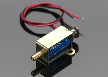
Solenoids are coils or electromagnetic actuators.
Examples:
-
The drive locks car doors;
-
Solenoid valves;
-
Electromagnet in metallurgical production;
-
The power plant of the Gaussian gun and more.
In any case, a typical circuit for connecting DC coils to a microcontroller or logic looks like this:

A transistor for amplifying the control current, the diode is connected in the opposite direction to protect the output of the microcontroller from bursts of self-induction EMF.
Input Devices and Sensors
You can control your system with buttons, resistors, encoders. Using the button, you can send a signal to the digital input of the arduino high (high / 5V) or low (low / 0V) level.
To do this, there are two options for inclusion. You need a normally-open button without fixing; for some purposes, you need a toggle switch or a button with fixing - choose for yourself, depending on the situation. To submit a unit, you need to connect the first contact of the button to the power source, and the second to the connection point of the resistor and the input of the microcontroller.
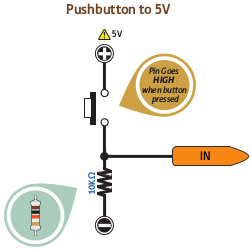
When the button is pressed on the resistance, the supply voltage drops, that is, a high level. When the button is not pressed, there is no current in the circuit, the potential on the resistor is low, the signal "Low / 0V" is applied to the input. This condition is called "pin is pulled to the ground, and the resistor is" pull-down ".
If you want the microcontroller to get 0 instead of 1 when you click on the button, connect the normally closed button in the same way or read on how to do it with normally open.
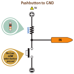
To give the microcontroller a command with a zero signal, the circuit changes slightly. One resistor leg is connected to the supply voltage, the second to the connection point of the normally-open button and the digital input of the arduino.
When the button is released all the voltage remains on it, the input gets a high level. This state is called "pin is pulled up to plus", and the resistor is "pull-up". When you press the button you are shunting (closing) the entrance to the ground.
Voltage divider and signal input from potentiometer and resistive analog
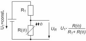
The voltage divider is used to connect variable resistances, such as thermistors, photoresistors, etc. Due to the fact that one of the resistors is constant, and the second variable - you can observe the voltage change at their midpoint, in the picture above it is indicated as Ur.
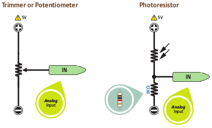
Thus, it is possible to connect various analog sensors of the resistive type and sensors which, under the influence of external forces, change their conductivity. As well as potentiometers.
In the picture below you see an example of connecting such elements. The potentiometer can be connected without an additional resistor, then in the extreme position there will be full voltage, but in the minimum position it is necessary to ensure stabilization or current limitation - otherwise it will short circuit.
conclusions
In order to connect any module and addition to the microcontroller without errors, you need to know the basics of electrical engineering, Ohm's law, general information about electromagnetism, as well as the basics of the operation of semiconductor devices. In fact, you can make sure that this is all much easier to do than listen to these complex words. Use the diagrams from this article in your projects!
See also at bgv.electricianexp.com
:
