Categories: Featured Articles » Practical Electronics
Number of views: 67360
Comments on the article: 7
Connecting and programming Arduino for beginners
Does studying microcontrollers seem complicated and incomprehensible? Before the appearance of Arudino, it was really not easy and required a certain set of programmers and other equipment.
What is an Arduino?
This is a kind of electronic constructor. The initial objective of the project is to allow people to easily learn how to program electronic devices, while devoting minimal time to the electronic part.
The assembly of the most complicated circuits and the connection of the boards can be carried out without a soldering iron, and with the help of jumpers with detachable connections “father” and “mother”. In this way, both attachments and expansion cards can be connected, which in the lexicon of arduinists are simply called “Shields”.

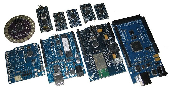
What is the first Arduino board to buy for a newbie?
The base and most popular board is considered Arduino uno. This fee resembles a credit card. Pretty big. Most shields that are on sale are perfect for her. There are sockets on the board for connecting external devices.

In domestic stores for 2017, its price is about 4-5 dollars. On modern models, Atmega328 is her heart.

Arduino board image and function decoding of each pin, Arduino UNO pinout
The microcontroller on this board is a long chip in the DIP28 package, which indicates that it has 28 legs.
The next most popular board costs almost two times cheaper than the previous one - 2-3 dollars. This is the board Arduino nano. Actual boards are built by the same Atmega328, they are functionally similar to UNO, there are differences in sizes and a matching solution with USB, more on this later. Another difference is that plugs are provided for connecting devices to the board, in the form of needles.

The number of pins (legs) of this board is the same, but you can observe that the microcontroller is made in a more compact TQFP32 package, ADC6 and ADC7 are added in the case, the other two “extra” legs duplicate the power bus. Its dimensions are quite compact - about the size of a thumb of your hand.
The third most popular board is Arduino Pro Mini, it does not have a USB port for connecting to a computer, I will tell you how to communicate a little later.

Arduino Nano vs Pro Mini Size Comparison
This is the smallest motherboard of all considered, otherwise it is similar to the previous two, and Atmega328 is still its heart. We will not consider other boards, since this is an article for beginners, and the comparison of boards is the topic of a separate article.
Arduino Pro Mini pinout, in the upper part, the USB-UART connection diagram, pin “GRN” - is wired to the reset circuit of the microcontroller, it may be called differently, for which you need to find out later.
Summary:
If UNO is convenient for prototyping, then Nano and Pro Mini are convenient for the final versions of your project, because they take up little space.

How to connect Arduino to a computer?
Arduino Uno and Nano connect to a computer via USB. At the same time, there is no hardware support for the USB port, a level conversion circuit solution, usually called USB-to-Serial or USB-UART (rs-232), is used here. At the same time, a special Arduino bootloader is flashed into the microcontroller, which allows flashing on these buses.
In Arduino Uno, this ligature is implemented on a microcontroller with USB support - ATmega16U2 (AT16U2). It turns out that the additional microcontroller on the board is needed for flashing the main microcontroller.
In Arduino Nano, this is implemented by the FT232R chip, or its analogue CH340. This is not a microcontroller - it is a level converter, this fact makes it easy to assemble the Arduino Nano from scratch with your own hands.
Typically, drivers are installed automatically when the Arduino board is connected. However, when I bought a Chinese copy of the Arduino Nano, the device was recognized, but it didn’t work, a round sticker with data on the release date was glued on the converter, I don’t know if it was done on purpose, but after peeling it off I saw the marking CH340.
Prior to this, I did not encounter this and thought that all USB-UART converters were assembled on FT232, I had to download drivers, they are very easy to find by request of “Arduino ch340 driver”. After a simple installation - it worked!
Through the same USB port, the microcontroller can also be powered, i.e. if you connect it to the adapter from a mobile phone, your system will work.
What should I do if my board does not have USB?
The Arduino Pro Mini is smaller. This was achieved by removing the USB connector for the firmware and the same USB-UART converter. Therefore, it must be purchased separately. The simplest converter on the CH340 (the cheapest), CPL2102 and FT232R, for sale costs from $ 1.
When buying, pay attention to what voltage this adapter is designed for. Pro mini is available in versions 3.3 and 5 V, a jumper is often located on the converters to switch the supply voltage.

When flashing the Pro Mini, just before it starts, you must click on RESET, however, in converters with DTR you do not need to do this, the connection diagram in the figure below.

They are joined by special terminals "Mama-Mama" (female-female).

Actually, all connections can be made using such terminals (Dupont), they are both on two sides with sockets, and with plugs, and on one side of the socket, and on the other plug.

How to write programs for Arduino?
To work with sketches (the name of the firmware is in the language of the arduino), there is a special integrated environment for developing the Arduino IDE, you can download it for free from the official website or from any thematic resource, usually there are no problems with installing it.

This is how the program interface looks. You can write programs in the simplified C AVR language specially developed for arduino, in fact it is a set of libraries called Wiring, as well as in pure C AVR. Using it facilitates the code and speeds up its work.
At the top of the window there is a familiar menu where you can open the file, settings, select the board you work with (Uno, Nano and many, many others) and also open projects with ready-made code examples. Below is a set of buttons for working with firmware, the keys you will see in the figure below.

At the bottom of the window is an area for displaying information about the project, the status of the code, firmware and the presence of errors.
Arduino IDE programming basics
At the beginning of the code, you need to declare variables and connect additional libraries, if they exist, this is done as follows:
#include biblioteka.h; // connect the library with the name “Biblioteka.h”
#define peremennaya 1234; // Declare a variable with a value of 1234
The Define command allows the compiler to choose the type of the variable, but you can set it manually, for example, an integer int, or a floating point float.
int led = 13; // created the variable “led” and assigned it the value “13”
The program can determine the state of the pin as 1 or 0. 1 is a logical unit, if pin 13 is 1, then the voltage on its physical leg will equal the supply voltage of the microcontroller (for arduino UNO and Nano - 5 V)
The digital signal is recorded using the digitalWrite command (pin, value), for example:
digitalWrite (led, high); // write the unit to pin 13 (we announced it above) log. Units.
As you can understand, the access to the ports is by numbering on the board, corresponding figure. Here is an example similar to the previous code:
digitalWrite (13, high); // set pin 13 to one
Often the sought-after time delay function is called by the delay () command, the value of which is set in milliseconds, microseconds are achieved using
delayMicroseconds () Delay (1000); // microcontroller will wait 1000 ms (1 second)
The port settings for input and output are set in the void setup {} function, with the command:
void setup () {
pinMode (NOMERPORTA, OUTPUT / INPUT); // arguments - variable name or port number, input or output to choose from
}
Void loop {}
Understanding the first Blink program
As a kind of “Hello, world” for microcontrollers, there is a LED flashing program, let's analyze its code:
In the beginning, with the pinMode command, we told the microcontroller to assign a port with an LED to the output.You have already noticed that the code does not declare the variable “LED_BUILTIN”, the fact is that in Uno, Nano and other boards from the factory, the built-in LED is connected to pin 13 and it is soldered to the board. It can be used by you for indication in your projects or for the simplest check of your flashing programs.
Next, we set the output to which the LED is soldered to unity (5 V), the next line makes the MK wait 1 second, and then sets the LED_BUILTIN pin to zero, waits a second and the program repeats in a circle, so when LED_BUILTIN is 1 - the LED ( and any other load connected to the port) is turned on, when at 0 it is turned off.
Does everything work and everything is clear? Then move on!
We read the value from the analog port and use the read data
The Atmega328 AVR microcontroller has a built-in 10-bit analog-to-digital converter. The 10-bit ADC allows you to read the voltage value from 0 to 5 volts, in increments of 1/1024 of the entire amplitude range of the signal (5 V).
To make it clearer, consider the situation, suppose the voltage value at the analog input is 2.5 V, then the microcontroller will read the value from pin "512" if the voltage is 0 - "0", and if 5 V - (1023). 1023 - because the count goes from 0, i.e. 0, 1, 2, 3, etc. up to 1023 - a total of 1024 values.
Here is how it looks in the code, using the standard sketch “analogInput” as an example
int sensorPin = A0;
int ledPin = 13;
int sensorValue = 0;
void setup () {
pinMode (ledPin, OUTPUT);
}
void loop () {
sensorValue = analogRead (sensorPin);
digitalWrite (ledPin, HIGH);
delay (sensorValue);
digitalWrite (ledPin, LOW);
delay (sensorValue);
}

The connection scheme of the potentiometer to Arduino, by analogy, the central output you can connect to any analog input.
Declare variables:
-
Ledpin - independently assign a pin with a built-in LED to the output and give an individual name;
-
sensorPin - analog input, set accordingly to the marking on the board: A0, A1, A2, etc .;
-
sensorValue - a variable for storing an integer read value and further work with it.
The code works like this: sensorValue save the analog value read with sensorPin (analogRead command). - here the work with the analog signal ends, then everything is as in the previous example.
We write the unit in ledPin, the LED turns on and wait for a time equal to the value of sensorValue, i.e. from 0 to 1023 milliseconds. Turn off the LED and wait again for this period of time, after which the code repeats.
Thus, by the position of the potentiometer, we set the flashing frequency of the LED.
Map function for Arudino
Not all functions for actuators (I do not know any) support “1023” as an argument, for example, the servo is limited by the angle of rotation, that is, by half a revolution (180 degrees) (half revolution) of the servo motor, the maximum argument of the function is “180”
Now about the syntax: map (the value we are translating is the minimum input, the maximum input, the minimum output, the maximum output).
In code, it looks like this:
(map (analogRead (pot), 0, 1023, 0, 180));
We read the value from the potentiometer (analogRead (pot)) from 0 to 1023, and at the output we get numbers from 0 to 180
Value Map Values:
-
0=0;
-
1023=180;
In practice, we apply this to the work of the same servo code, take a look at the code with the Arduino IDE, if you carefully read the previous sections, then it does not require explanation.
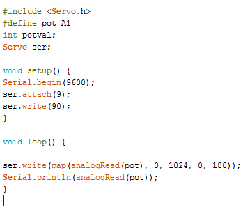
And the connection diagram.

Conclusions Arduino is a very convenient tool for learning how to work with microcontrollers. And if you use pure C AVR, or as it is sometimes called “Pure C”, you will significantly reduce the code weight and fit more in the microcontroller’s memory, as a result, you will get an excellent factory-made debugging board with USB firmware.

Opinion of the author:
I like arduino. It is a pity that many experienced microcontroller programmers criticize it unreasonably, that it is too simplified. In principle, only the language is simplified, but no one forces you to use it, plus you can flash the microcontroller through the ICSP connector and fill in the code you want without any bootloaders that you don’t need.
For those who want to play with electronics, as an advanced constructor, it is perfect, but for experienced programmers, a board that does not require assembly will also be useful!
For more information about Arduino and the features of its use in various schemes, see the e-book -Arduino for dummies. Illustrated practical guide.
See also at i.electricianexp.com
: