Categories: Microcontroller circuits
Number of views: 41940
Comments on the article: 5
Methods for reading and managing Arduino I / O ports
To interact with the outside world, you need to configure the outputs of the microcontroller to receive or transmit a signal. As a result, each pin will work in the input and output mode. There are two ways to do this on every Arduino board you love, exactly how you learn from this article.
Method One - The Standard Language for the Arduino IDE
Everyone knows that Arduino It is programmed in C ++ with some adaptation and simplifications for beginners. It is called Wiring. Initially, all arduino ports are defined as inputs, and there is no need to specify this in the code.
Ports are usually written in the variable initialization function:
void setup ()
{
// the code
}
The pinMode command is used for this, it has a fairly simple syntax, first the port number is indicated, then its role is separated by commas.
pinMode (nomer_porta, naznachenie)
With this command, the internal circuitry of the microcontroller is configured in a specific way.
There are three modes in which the port can work: INPUT - input, in this mode occurs reading data from sensors, button status, analog and digital signal. The port is located in the so-called high-impedance state, in simple words - the input has high resistance. This value is set, for example, 13 pin of the board, if necessary, as follows:
pinMode (13, INPUT);
OUTPUT - output, depending on the command prescribed in the code, the port takes a value of one or zero. The output becomes a kind of controlled power source and produces a maximum current (in our case, 20 mA and 40 mA at the peak) connected to the load. To assign a port as an output to Arduino you need to enter:
pinMode (13, OUTPUT);
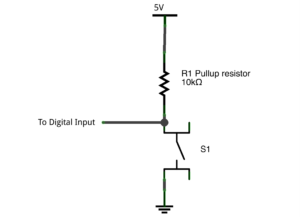
INPUT_PULLUP - the port works as an input, but the so-called connects to it. 20 kΩ pull-up resistor.
The conditional internal circuitry of the port in this state is shown below. A feature of this input is that the input signal is perceived as inverted (the “unit” at the input is perceived by the microcontroller as “zero”). In this mode, you can not use external pull-up resistors when working with buttons.
pinMode (13, INPUT_PULLUP);
Data is received from the ports and transmitted to them by the commands:
-
digitalWrite (pin, value) - converts the output pin to logical 1 or 0, respectively, 5V voltage appears or disappears at the output, for example digitalWrite (13, HIGH) - supplies 5 volts (logical unit) to 13 pins, and digitalWrite (13, low ) - translates 13 pins into a state of logical zero (0 volts);
-
digitalRead (pin) - reads the value from the input, example digitalRead (10), reads the signal from 10 pins;
-
analogRead (pin) - reads an analog signal from an analog port, you get a value in the range from 0 to 1023 (within a 10-bit ADC), an example is analogRead (3).
Method two - manage ports through Atmega registers and speed up code
Such control is of course simple, but in this case there are two drawbacks - greater memory consumption and poor performance when working with ports. But remember what is Arduino, regardless of the option board (uno, micro, nano)? First of all, this microcontroller AVR family ATMEGA, recently used MK atmega328.
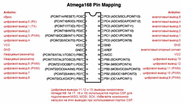
In the Arduino IDE, you can program in the native language for this family of C AVR, as if you were working with a separate microcontroller. But first things first. To manage Arduino ports this way, you first need to carefully consider the following illustration.
Perhaps someone will more clearly examine the ports in this form (the same in the figure, but in a different design):
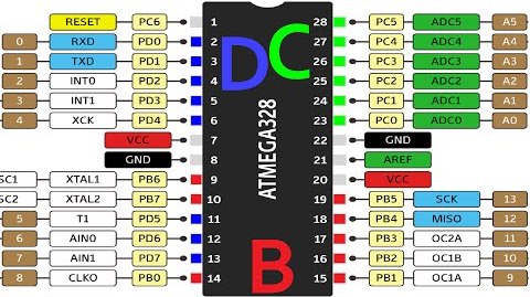
Here you see the correspondence of the conclusions of Arduino and the names of the ports of Atmega. So, we have 3 ports:
-
PORTB;
-
PORTC;
-
PORTD.
Based on the images shown, I compiled a table of correspondence between the ports of Arduino and Atmega, it will be useful to you in the future.
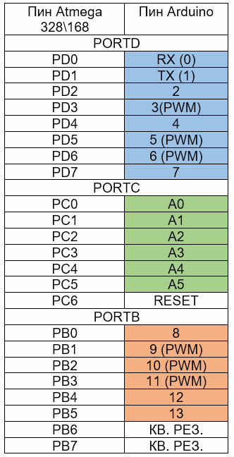
Atmega has three 8-bit registers that control the state of the ports, for example, port B will figure out their purpose by drawing analogies with the standard wiring tools described at the beginning of this article:
-
PORTB - Manage output status. If the pin is in the "Output" mode, then 1 and 0 determine the presence of the same signals at the output. If the pin is in the “Input” mode, then 1 connects a pull-up resistor (same as the INPUT_PULLUP discussed above), if 0 is a high-impedance state (analogue of INPUT);
-
PINB is a read register. Accordingly, it contains information about the current state of the port pins (logical unit or zero).
-
DDRB - port direction register. With it, you indicate to the microcontroller whether the port is an input or an output, with “1” an output and “0” an input.
Instead of the letter “B”, there may be any other according to the names of the ports, for example, PORTD or PORTC other commands work similarly.
We blink the LED, replace the standard digitalWrite () function. First, let's recall what the original example from the Arduino IDE library looks like.
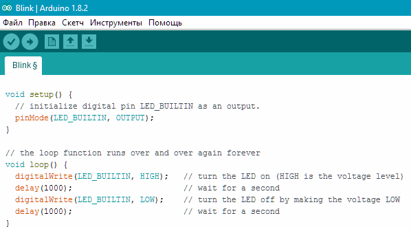
This is the code of the well-known “blink”, which shows the blinking of the LED built into the board.
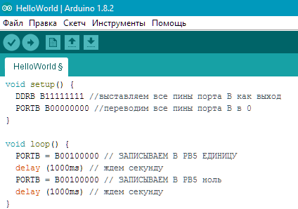
The comments explain the code. The logic of this work is as follows.
The PORTB B00100000 command puts PB5 in the state of a logical unit, look, and those pictures and the table below are located and we see that PB5 corresponds to 13 pin of Arduina.
The letter "B" in front of the numbers indicates that we are writing the values in binary form. Numbering in binary goes from right to left, i.e. here the unit is in the sixth bit from the right edge of the bit, which tells the microcontroller about the interaction with the state of the sixth bit of the port B register (PB5). The table below shows the structure of port D, it is similar and is given as an example.

You can set the value not in binary, but in hexadecimal form, for example, for this we open the windows calculator and in the “VIEW” mode, select the “Programmer” option.
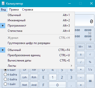
Enter the desired number:
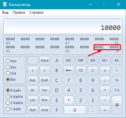
And click on HEX:
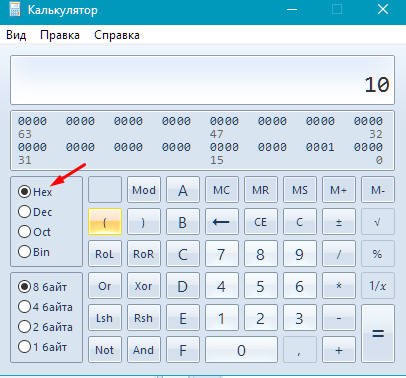
In this case, we transfer all this to the Arduino IDE, but instead of the prefix "B" it will be "0x".

But with this input there is a problem. If you have anything connected to other pins, then entering a command like B00010000 - you will reset all pins except 13 (PB5). You can enter data for each pin individually. It will look like this:
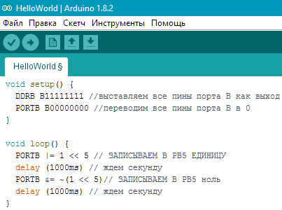
Such a record may seem incomprehensible, let's figure it out.
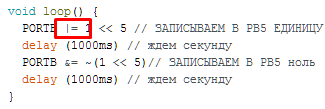
This is a logical addition operation, | = means adding something to the contents of the port.

This means that you need to add a word of 8 bits in the register with a unit shifted by 5 bits - as a result, if 11000010 turns out to be 110,110,010. In this example, it can be seen that only PB5 has changed, the remaining bits of this register have remained unchanged, as well as The state of the microcontroller pins remained unchanged.
But with logical addition, a problem arises - you cannot turn the unit into zero, because:
0+0=1
1+0=1
0+1=1
Logical multiplication and inversion will come to our aid:

& = means to multiply the contents of the port by a specific number.

And this is the number by which we multiply. The “~” sign indicates inversion. In our case, the inverted unit is zero. That is, we multiply the contents of the port by zero, shifted by 5 bits. For example, it was 10110001, it became 10100001. The remaining bits remained unchanged.

The same can be done using the invert operation (^):
Reading from ports, the analog of digitalRead () is performed using the PIN register, in practice it looks like this:
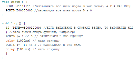
Here we check whether the expression in parentheses is equal to the real state of the ports, i.e. similarly if we wrote if (digitalRead (12) == 1).
Conclusion
Why are there such difficulties with port management if you can use standard convenient functions? It's all about speed and code size. When using the second method, discussed in the article, the code size is significantly reduced, and the speed increases by several orders of magnitude. The standard digitalWrite () was performed in 1800 μs, and recording directly to the port in 0.2 μs, and digitalRead () in 1900 μs, and also became 0.2 μs. This control method was found on the open spaces of the network and is often found in code. finished projects.
See also at i.electricianexp.com
:

