Categories: Home automation, Microcontroller circuits
Number of views: 17351
Comments on the article: 0
Microcontroller Remote Control: IR Remote, Arduino, ESP8266, 433 MHz
The issue of remote or remote control of electrical equipment has always been and will be relevant, regardless of whether there are automation tools in the system or not. For the organization of remote control, it does not matter at all whether microcontroller, it all depends on the necessary functions assigned to the managed device. In this article, you will learn general information about how to remotely control a microcontroller.
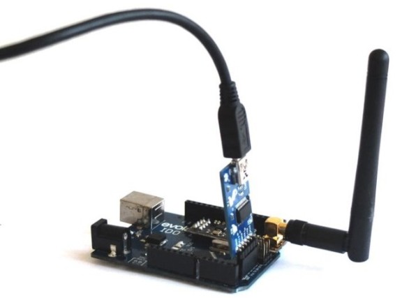
Kinds
There are two main types of remote communication:
Wired. When the control of actuators located in one room (or not the room) is carried out from the control panel or from a button post located in another place. In this case, an electrical wire connection of the control circuits and actuators (relays, contactors, which include mechanisms, such as motors or systems, for example, lighting) is provided.
Wireless. In this embodiment, no electrical connection of the control and executive circuits is required. In wireless circuits, there are two devices: a transmitter or a remote control (RC) and a receiver, which is part of the controlled circuit. Wireless control, in turn, is common in two versions:
-
By optical signal. Such systems are in every home, so you control the operation of the TV, air conditioning and other household appliances.
-
By radio signal. There are already a number of options: Bluetooth, ZigBee, Wi-Fi, 433 MHz transmitter-receivers and other variations on this subject.
It is worth noting that with modern technical means you can control the microcontroller, both from the remote control and through the Internet on a local network or with access from anywhere in the world.
IR remote
We begin our consideration with the simplest and most classic version. Device control by transmitting a code from the flickering sequence of an IR LED to an optical receiver installed on the device It is worth noting that the infrared spectrum is not visible to the human eye, but most photo and video cameras see it.
Since most cameras see infrared, you can check serviceability of remote controls. To do this, simply point the remote control so that the emitter looks into the camera and press the buttons. Usually, a white glow with a purple tint is visible on the screen.
This control has an obvious drawback - you must point the remote towards the receiver. And if the batteries in the remote control are run out, then you also have to aim, since the operations are becoming less and less.
Advantages are simplicity, high maintainability, both the transmitter and the receiver. You can find the details by dismantling the broken remotes and televisions in order to apply this in your own projects.
A typical sensor is as follows. Since the optical signal is being received, it is necessary to exclude triggering from extraneous light sources, such as the sun, lighting lamps, and others. It is also worth noting that the infrared signal is received mainly at a frequency of 38 kHz.
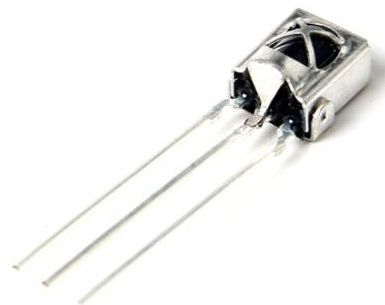
Here are the specifications of one of the IR sensors:
-
carrier frequency: 38 kHz;
-
supply voltage: 2.7 - 5.5 V;
-
current consumption: 50 μA.
And its connection diagram:
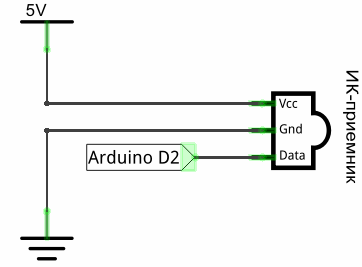
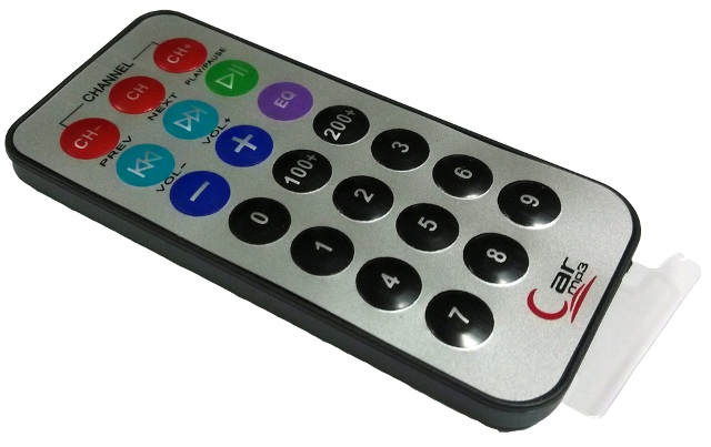
The remote control can be used by anyone with a similar principle of operation, remote controls from:
-
TVs
-
DVD players
-
radio tape recorders;
-
from modern lighting devices, such as smart chandeliers and LED strips and more.
Here is an example of using such a sensor with Arduino:
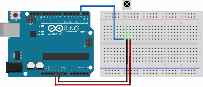
In order for the microcontroller, in our case Arduin, to understand the signal from the sensor, you need to use the IRremote.h library. For an example of how to read a signal from a sensor, here is a code for recognizing them by reading the serial port of the microcontroller from the Arduino IDE:
#include "IRremote.h" // connect the library to work with the IR signal.
IRrecv irrecv (2); // indicate the output to which the receiver is connected
decode_results results;
void setup () {
Serial.begin (9600); // set the COM port speed
irrecv.enableIRIn (); // start the reception
}
void loop () {
if (irrecv.decode (& results)) {// if the data came
Serial.println (results.value, HEX); // print data
irrecv.resume (); // accept the following command
}
}
As a result, when you flash the arduino, and begin to “shine” into the receiver with the remote control, we will see the following picture in the serial port monitor:
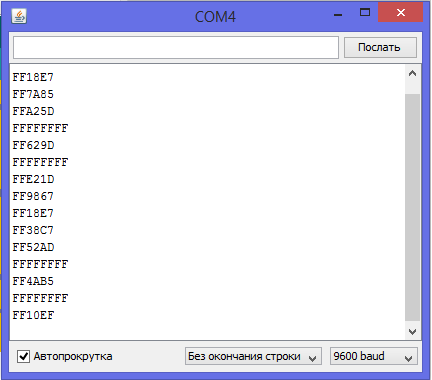
These are codes that send buttons in hexadecimal form. Thus, you can find out which button on the remote control which code sends, so there are no specific requirements for the remote control used, because you can recognize and associate any. By the way, this is an idea for a project of a trained universal remote control, such were sold earlier. But now in the age of the Internet, the amount of technology controlled in this way is decreasing every year.
And with this code, you can recognize signals and manage the load:
#include "IRremote.h"
IRrecv irrecv (2); // indicate the output to which the receiver is connected
decode_results results;
void setup () {
irrecv.enableIRIn (); // start the reception
}
void loop () {
if (irrecv.decode (& results)) {// if the data came
switch (results.value) {
case 0xFFA857:
digitalWrite (13, HIGH);
break;
case 0xFFE01F:
digitalWrite (13, LOW);
break;
    }
  irrecv.resume (); // accept the following command
  }
}
The main thing in the code is recognition through the Switch function, sometimes they are called a “switchcase”. It is an analog of the if branches, but has a more beautiful form for perception. Case - these are the options, "if such a code arrives, then ..." In the code, 13 pins are controlled for certain signals. Let me remind you that the built-in LED on the ARDUINO board is connected to pin 13, i.e. the author of the code controlled the LED.
You can control anything using a high or low digital pin through a power transistor (which we covered in two articles earlier here and here) with a direct current load, or through a triac and a driver for it with a direct current load, you can also use relays and contactors, in general, a whole field for imagination.
Radio signal reception and transmission
For use with microcontrollers, transmitters with operating frequencies of 433 MHz or 315 MHz are common, there may be other frequencies, depending on the specific board, but these are the most common. The system consists of two nodes - a receiver and a transmitter, which is logical.
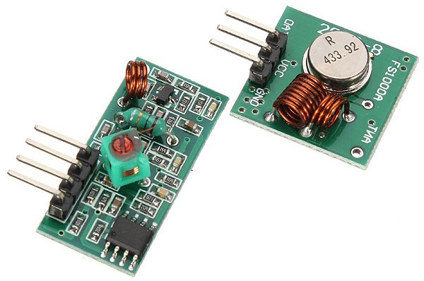
In the picture, the transmitter is shown at the top right, and the receiver at the bottom left. Their name for the search: 433MHz radio module, MX-05V / XD-RF-5V (receiver and transmitter).
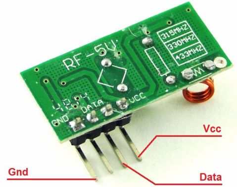
The pinout, as is often the case in modules, is painted on the board, like the transmitter:
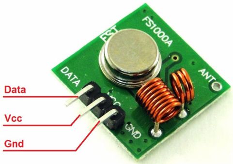
The receiver is not so obvious, because Data on the printed circuit board is written over two pins, in fact one of them is not used.
For example, we give a diagram and a code for turning on the LED from one Arduino board connected to another similar board, without wires. The receiver and transmitter are connected in the same way to both boards:
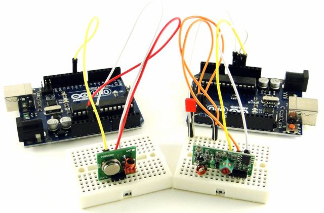
Device
Module
Arduino pins
Receiver
Vcc
GND
DATA
+ 5V
GND
2
Transmitter
Vcc
GND
DATA
+ 5V
GND
2
Next, you need to connect the RCswitch.h library to the Arduino IDE
To start, we write the transmitter program:
#include
RCSwitch mySwitch = RCSwitch(); // create an object to work with the front-end
void setup () {
mySwitch.enableTransmit(2); // tell the program which pin the information channel is connected to
}
void loop () {
mySwitch.send (B0100,4);
delay (1000);
mySwitch.send (B1000, 4);
delay (1000);
}
The transmitter can transmit binary code, but its values can be written in decimal form.
mySwitch.send (B0100,4);
and
mySwitch.send (B1000, 4);
these are the transfer commands, mySwitch is the name of the transmitter that we indicated at the beginning of the code, and send is the transfer command. The arguments for this function are:
Transmitter name.send (value, packet size of pulses sent to the air);
B1000 - the symbol B - means binary, it could be written as the number 8, i.e. in decimal notation. Another option was to write “1000” as a string (in quotation marks).
Next, we write the code for the receiver (it is flashed into the board to which the receiver is connected):
#include
RCSwitch mySwitch = RCSwitch ();
void setup () {
pinMode (3, OUTPUT);
mySwitch.enableReceive (0);
}
void loop () {
if (mySwitch.available ()) {
int value = mySwitch.getReceivedValue ();
if (value == B1000)
digitalWrite (3, HIGH);
else if (value == B0100)
digitalWrite (3, LOW);
mySwitch.resetAvailable ();
}
}
Here we declare that the accepted value is stored in the Value variable in the string mySwitch.getReceivedValue (). And the fact that the receiver is connected to the 2nd pin is described here by mySwiitch.enableReceive (0).
Otherwise, the code is elementary, if signal 0100 is received, then pin number 3 is set to high (log. Unit), and if 1000, then to low (log. Zero).
Interesting:
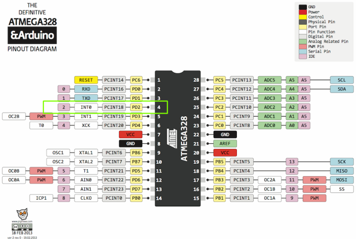
In the line mySwitch.enableTransmit (0) we tell the program that the receiver is connected to the 2nd pin and the receive mode is turned on. The most attentive ones noticed that the argument of this method is not pin number “2”, but “0”, the fact is that the enableTransmit method (number) does not accept the pin number, but the interrupt number, but in atmega328, which is put on Arduino Uno, nano, promini and several others, on the second pin (PortD pin PD2) hangs an interrupt with the number zero. You can see this in the Atmega pinout applicable to the Arduino board, the pin numbers are written in pink boxes.
This method of transmitting and receiving is very simple and cheap; a pair of receiver and transmitter costs about $ 1.5 at the time of writing.
Wi-Fi, Adruino and ESP8266
Let's begin with ESP8266 is a microcontroller with hardware support for Wi-Fi, It is sold as a separate chip, and soldered to the board, like an arduino. It has a 32-bit kernel, it is programmed through a serial port (UART).
The boards usually have 2 or more free GPIO pins and there are always pins for firmware, this must be done via a USB to serial adapter. Managed by AT teams, a full list of commands can be found on the official ESP8266 website and on github.
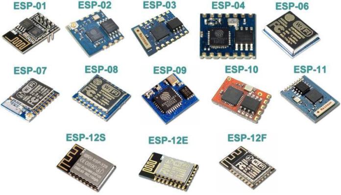
There is a more interesting option, NodeMCU boards, they have the ability to flash via USB, because A USB-UART converter is already on the board, usually made on a CP2102 chip. Node MCU is a firmware, something like an operating system, a project based on the Lua scripting language.
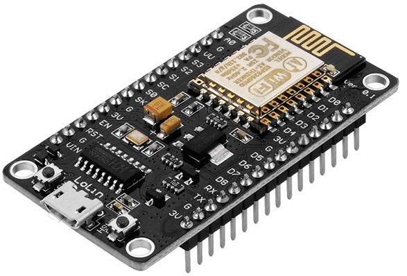
The firmware can execute Lua scripts, either by accepting them on a serial port or by reproducing algorithms stored in Flash memory.
By the way, it has its own file system, although there are no directories in it, i.e. only files without folders. In memory, not only scripts can be stored, but also various data, i.e. the board can store information recorded, for example, from sensors.
The board works with interfaces:
-
1-Wire;
-
I2C;
-
SPI
-
UART.
It has a whole host of functions:
-
encryption module;
-
task Manager;
-
real time clock;
-
clock synchronization protocol via Internet SNTP;
-
timers;
-
ADC channel (one);
-
play audio files;
-
generate at the outputs a PWM signal (up to 6);
-
use sockets, there is support for FatFS, i.e. you can connect SD cards and so on.
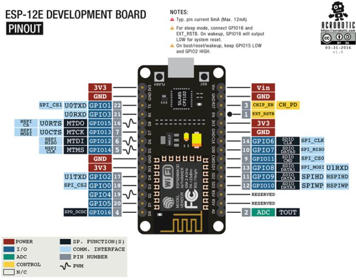
And here is a short list of what the board can work with:
-
accelerometers ADXL345;
-
HMC5883L magnetometers
-
gyroscopes L3G4200D;
-
temperature and humidity sensors AM2320, DHT11, DHT21, DHT22, DHT33, DHT44;
-
sensors of temperature, humidity, atmospheric pressure BME280;
-
temperature and atmospheric pressure sensors BMP085;
-
many displays working on I2C, SPI buses. With the ability to work with different fonts;
-
TFT displays ILI9163, ILI9341, PCF8833, SEPS225, SSD1331, SSD1351, ST7735;
-
smart LEDs and LED controllers - WS2812, tm1829, WS2801, WS2812.
In addition to using the Lua language, you can program the board from under the Arduino IDE.
ESP8266 can be used as a standalone device or as a module for wireless communication with Arduino.
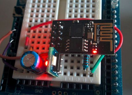
Consideration of all the functions and features of this board will take a whole series of articles.
So this board is a great option for remote control via Wi-Fi. The scope is enormous, for example, to use a smartphone as a control panel for a makeshift radio-controlled machine or quadrocopter, remote lighting control, up to arranging networks for the whole house and manage each outlet, lamp, etc. if only there were enough pins.
The simplest way to work with the microcontroller is to use a single ESP8266 board. Below is a diagram of a simple wi-fi outlet.
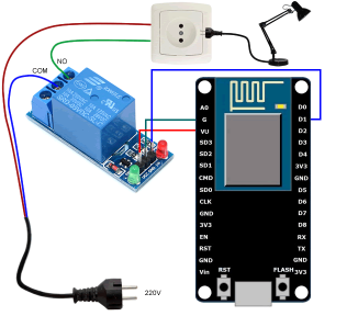
To assemble this circuit, you need a relay module, or a conventional relay connected to a pin through a transistor. First you need a program for a smartphone RoboRemoFree,. In it, you will configure the connection to the ESP and make an interface for controlling the outlet. To describe how to use it, you need to write a separate article, so let’s omit this material for now.
In ESP we load the following firmware, through the ESPlorer program (program for working with the board)
--Wifi AP Settup
wifi.setmode (wifi.STATIONAP)
cfg = {}
cfg.ssid = "ESPTEST"
cfg.pwd = "1234567890"
wifi.ap.config (cfg)
--Set Pin mode
my_pin_nummber = 1
--gpio.mode (my_pin_nummber, gpio.OUTPUT)
gpio.mode (my_pin_nummber, gpio.OPENDRAIN)
--Create Server
sv = net.createServer (net.TCP)
function receiver (sck, data)
if string.sub (data, 0, 1) == "1" then
--gpio.write (my_pin_nummber, gpio.HIGH)
gpio.write (my_pin_nummber, gpio.LOW)
else if string.sub (data, 0, 1) == "0" then --gpio.write (my_pin_nummber, gpio.LOW) gpio.write (my_pin_nummber, gpio.HIGH) end end print (data) end if sv then sv: listen (333, function (conn) conn: on ("receive", receiver) conn: send ("Hello!") end) end --Create HTTP Server http = net.createServer (net.TCP) function receive_http (sck, data) print (data) local request = string.match (data, "([^ \ r, \ n] *) [\ r, \ n]", 1) if request == 'GET / on HTTP / 1.1' then --gpio.write (my_pin_nummber, gpio.HIGH) gpio.write (my_pin_nummber, gpio.LOW) end if request == 'GET / off HTTP / 1.1' then --gpio.write (my_pin_nummber, gpio.LOW) gpio.write (my_pin_nummber, gpio.HIGH) end sck: on ("sent", function (sck) sck: close () collectgarbage () end) local response = "HTTP / 1.0 200 OK \ r \ nServer: NodeMCU on ESP8266 \ r \ nContent-Type: text / html \ r \ n \ r \ n" .. "
"
NodeMCU on ESP8266
" .."
" ..
" "
sck: send (response)
end
if http then
http: listen (80, function (conn)
conn: on ("receive", receive_http)
end)
end
print ("Started.")
Now you can control the program either from the Roboremo program, or through any web browser, for this you need to type the IP address of the board in the address bar in the wi-fi mode, it 192.168.4.1.
There is a snippet in the code:
"
" NodeMCU on ESP8266
" ..
"
" ..
" "
This is a kind of response that is issued to the browser when accessing the board. It contains HTML code, i.e. The simplest web page, similar to the one on which you are reading this article.
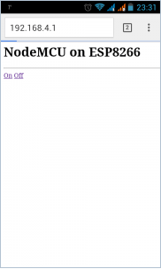
Here is this page, launched in the browser of a smartphone running Android OS. The above is not a complete instruction, since it would take a huge amount, if you are interested in this information - write comments and we will definitely conduct a review and write an article about working with it.
See also at bgv.electricianexp.com
:
