Categories: Featured Articles » Practical Electronics
Number of views: 49294
Comments on the article: 0
How does the conversion of the analog signal to digital
In electronics, signals are divided into: analog, discrete and digital. To begin with, all that we feel, see, hear, for the most part, is an analog signal, and what a computer processor sees is a digital signal. It doesn’t sound quite clear, so let's deal with these definitions and how one type of signal is converted to another.
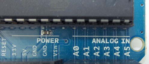
Signal types
In electrical representation, an analog signal, judging by its name, is an analog of a real value. For example, you feel the temperature of the environment constantly, throughout your life. There are no breaks. At the same time, you feel not only two levels of “hot” and “cold”, but an infinite number of sensations that describe this value.
For a person, “cold” can be different, it is autumn coolness and winter frost, and light frosts, but not always “cold” is a negative temperature, just like “warm” is not always a positive temperature.
It follows that the analog signal has two features:
1. Continuity in time.
2. The number of signal values tends to infinity, ie An analog signal cannot be precisely divided into parts or calibrated by breaking the scale into specific sections. Measurement methods - based on the unit of measurement, and their accuracy depends only on the price of the division of the scale, the smaller it is, the more accurate the measurement.
Discrete signals - these are signals that are a sequence of reports or measurements of any magnitude. Measurements of such signals are not continuous, but periodic.
I will try to explain. If you installed a thermometer somewhere, it measures an analog value - this follows from the above. But you, actually following his testimonies, get discrete information. Discrete means separate.
For example, you woke up and found out how many degrees the thermometer had, the next time you looked at it at a thermometer at noon, and the third time in the evening. You do not know how fast the temperature changed, evenly, or by a sharp jump, you only know the data at that moment in time that you observed.
Digital signals Is a set of levels, types 1 and 0, high and low, whether or not. The depth of reflection of information in digital form is limited by the bit depth of a digital device (a set of logic, a microcontroller, processor etc.) It turns out that it is ideal for storing Boolean data. An example, you can give the following, for storing data such as "Day" and "Night", just 1 bit of information is enough.
Bit - this is the minimum value of representing information in digital form, it can only store two types of values: 1 (logical unit, high level), or 0 (logical zero, low level).
In electronics, a bit of information is represented in the form of a low voltage level (close to 0) and a high voltage level (depending on a particular device, often coincides with the supply voltage of a given digital node, typical values are 1.7, 3.3. 5V, 15V).
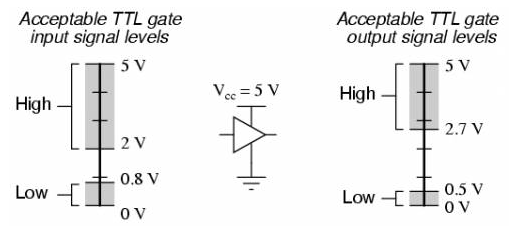
All intermediate values between the accepted low and high levels are a transition region and may not have a specific value, depending on the circuitry, both the device as a whole and the internal circuit of the microcontroller (or any other digital device) may have a different transition level, for example, for 5 -volt logic, the voltage values from 0 to 0.8V can be taken as zero, and from 2V to 5V as a unit, while the gap between 0.8 and 2V is an undefined zone, in fact, it helps to separate zero from unity.
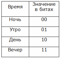
The more accurate and capacious values you need to store, the more bits you need, we give an example table with a digital display of four values of the time of day:
Night - Morning - Day - Evening
For this, we need 2 bits:
Analog to digital conversion
In the general case, analog-to-digital conversion is the process of converting a physical quantity into a digital value. The digital value is a set of units and zeros perceived by the processing device.
Such a transformation is necessary for the interaction of digital technology with the environment.
Since the analogue electrical signal repeats the input signal in its form, it cannot be recorded digitally “as it is” because it has an infinite number of values. An example is the sound recording process. It in its original form looks like this:
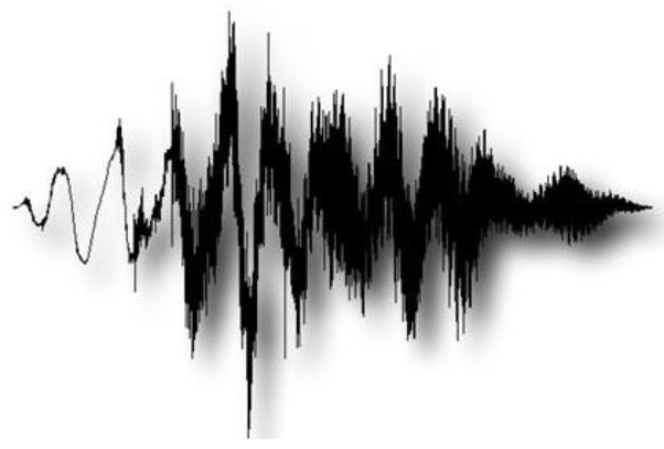
It is the sum of waves with different frequencies. Which, when decomposing in frequencies (for more details, see Fourier transforms), one way or another, can be brought closer to a similar picture:
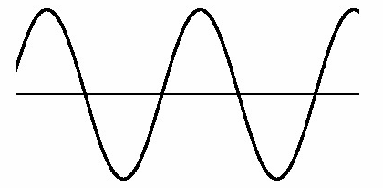
Now try to present it in the form of a set of the type “111100101010100”, it’s rather difficult, isn't it?
Another example of the need to convert an analog quantity to a digital one is its measurement: electronic thermometers, voltmeters, ammeters and other measuring instruments interact with analog quantities.
How is the conversion going?
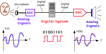
First, look at the diagram of a typical conversion of an analog signal to digital and vice versa. Later we will return to her.

In fact, this is a complex process, which consists of two main stages:
1. Discretization of the signal.
2. Quantization by level.
Discretization of a signal is the determination of the time intervals over which the signal is measured. The shorter these gaps, the more accurate the measurement. The sampling period (T) is the length of time from the beginning of reading data to its end. Sampling rate (f) is the reciprocal of:
fd = 1 / T
After reading the signal, it is processed and stored in memory.
It turns out that during the time that the readings of the signal are read and processed, it can change, thus, the measured value is distorted. There is such a Kotelnikov theorem and the following rule follows from it:
The sampling frequency should be at least 2 times greater than the frequency of the sampled signal.
This is a screenshot from Wikipedia, with an excerpt from the theorem.

To determine the numerical value, quantization by level is necessary. Quantum is a certain range of measured values, averaged reduced to a certain number.
X1 ... X2 = Xy
Those. signals from X1 to X2, conditionally equated to a specific value of Xy. This resembles the division price of a pointer meter. When you take readings, you often equate them to the nearest mark on the scale of the instrument.
So with quantization by level, the more quanta, the more accurate measurements and the more decimal places (hundredths, thousandths and so on) they can contain.
More precisely, the number of decimal places is rather determined by the resolution of the ADC.

The picture shows the process of quantization of a signal using one bit of information, as I described above, when, when a certain limit is exceeded, a high level value is accepted.
On the right is the quantization of the signal, and a record in the form of two data bits. As you can see, this signal fragment is already divided into four values. It turns out that as a result, a smooth analog signal turned into a digital "step" signal.
The number of quantization levels is determined by the formula:

Where n is the number of bits, N is the quantization level.
Here is an example of a signal broken into a larger number of quanta:
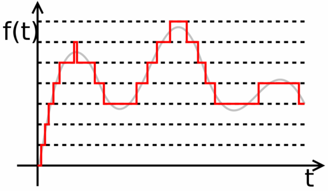
This very clearly shows that the more often the signal values are taken (the higher the sampling frequency), the more accurately it is measured.
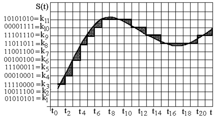
This image shows the conversion of an analog signal into a digital form, and to the left of the ordinate axis (vertical axis) is an 8-bit digital recording.
Analog to Digital Converters
An ADC or an analog-to-digital converter can be implemented as a separate device or be integrated into microcontroller.
Previously, microcontrollers, for example, the MCS-51 family, did not contain an ADC, an external microcircuit was used for this, and it became necessary to write a subroutine for processing the values of an external IC.
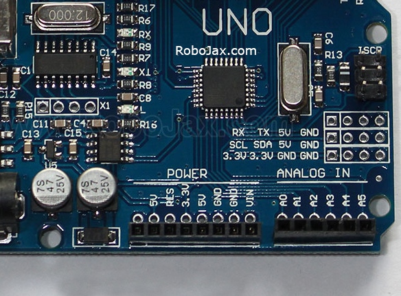
Now they are in most modern microcontrollers, for example AVR AtMEGA328, which is the basis of most popular circuit board Arduino, it is built into MK itself. In Arduino, reading analog data is simple with the AnalogRead () command. Although the microprocessor, which is installed in the same no less popular Raspberry PI, does not have it, so not everything is so simple.
In fact, there are a large number of options for analog-to-digital converters, each of which has its own disadvantages and advantages. Describing which within this article does not make much sense, since this is a large amount of material. Consider only the general structure of some of them.
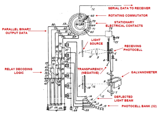
The oldest patented ADC option is Paul M. Rainey's patent, “Facsimile Telegraph System,” U.S. Patent 1,608,527, Filed July 20, 1921, Issued November 30, 1926. This is a 5-bit direct conversion ADC. From the name of the patent, thoughts come that the use of this device was connected with the transmission of data via telegraph.
If we talk about modern direct conversion ADCs have the following scheme:
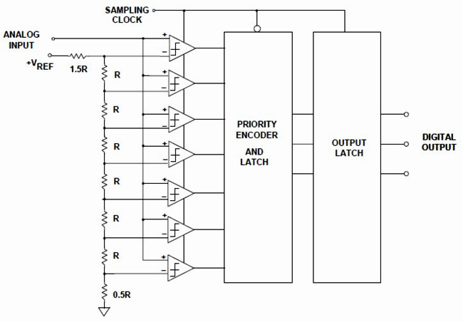
This shows that the input is a chain from comparatorswhich output their signal when they cross some threshold signal. This is bit depth and quantization. Anyone even a little strong in circuitry, saw this obvious fact.
Who is not strong, then the input circuit works this way:
An analog signal is input to the “+” input, all at once. The outputs with the designation “-” receive the reference voltage, which is decomposed using a series of resistors (resistive divider) into a number of reference voltages. For example, a series for this chain looks like this ratio:
Urefi = (1/16, 3/16, 5/16, 7/16, 9/16, 11/16, 13/16) * Uref
In brackets, a comma indicates what part of the total reference voltage Uref is supplied to the input of each input voltage.
Those. each of the elements has two inputs when the input voltage is signed «+» exceeds the input voltage with a “-" sign, a logical unit appears at its output. When the voltage at the positive (non-inverting) input is less than at the negative (inverting) input, then the output is zero.

The voltage is divided so that the input voltage is divided into the desired number of digits. When the voltage at the input reaches the output of the corresponding element, a signal appears, the processing circuit outputs the “correct” signal in digital form.
Such a comparator is good at data processing speed, all elements of the input circuit are triggered in parallel, the main delay of this type of ADC is formed from the delay of 1 comparator (they are simultaneously triggered simultaneously) and the delay is encoder.
However, there is a huge drawback of parallel circuits - this is the need for a large number of comparators to obtain high-resolution ADCs. To get, for example, 8 digits, you need 2 ^ 8 comparators, and this is as many as 256 pieces. For a ten-bit (in Arduino 10-bit ADC, by the way, but of a different type), you need 1024 comparators. Judge for yourselves the appropriateness of such a treatment option, and where it may be needed.
There are other types of ADCs:
-
consecutive approximation;
-
delta sigma ADC.
Conclusion
Converting an analog signal to digital is necessary for reading parameters from analog sensors. There is a separate type of digital sensors, they are either integrated circuits, for example DS18b20 - at its output there is already a digital signal and it can be processed by any microcontrollers or microprocessors without the need for an ADC, or an analog sensor on a board that already has its own converter. Each type of sensor has its own pros and cons, such as noise immunity and measurement error.
Knowledge of the principles of conversion is necessary for everyone who works with microcontrollers, because not even every modern system has such converters built in, you have to use external microcircuits. For example, we can cite such a board designed specifically for the Raspberry PI GPIO connector with precision ADC on ADS1256.
See also at bgv.electricianexp.com
:
