Categories: Featured Articles » Home automation
Number of views: 36024
Comments on the article: 7
Water leakage protection block - industrial detectors and home-made devices
 Water will find a hole. This proverb is known to all. The most important thing is that it is confirmed, albeit not very often, but the consequences can be the most deplorable. Here we will talk about what the leakage of water or sewer pipes in the apartment is fraught with. Often, we learn about these cases from an angry neighbor living on the floor below.
And, as a rule, the flooding of the lower neighbors occurs just after they made an expensive renovation, because they don’t do anything else now. Here you can see anything: a sagging and collapsed stretch ceiling, wallpaper behind the walls, a surfaced parquet or expanded linoleum, under which a warm floor was laid. And it’s not at all good for the flood to go for electrical wiring.
The drafting of acts begins, the circulation in the courts and house management companies. Repeated repairs are done, of course, at the expense of the upper neighbor. And it is better not to remember completely spoiled relationships and spent nerves.
All this might not have happened if a leak were noticed at an early stage. After all, most often it all starts with individual harmless drops that are difficult to notice. Gradually, these drops turn into a thin stream, and then a pipe breaks or a gasket simply breaks out, and troubles can not be avoided.
Of course, modern plastic pipes have a guarantee for fifty years, but where did they stand for so many pipes, who can attest to it personally? Therefore, an accident can happen at the most inopportune moment. But is it appropriate at all in this case to talk about some suitable moment?
To prevent the "global flood", all kinds of sensors and leakage alarms are used. The problem, apparently, is so acute that in recent years various devices have begun to be produced by the industry to help deal with leaks.
The complexity and functionality of such devices, more precisely, their range, is very wide. It can be simple signaling devices that inform about leakage with a sound signal, more complex devices can block water in the whole apartment.
The simplest “tweeters” are self-powered by batteries, the more complex ones, of course, are powered by the mains. There are even devices that can notify the owner of an apartment by accident on their cell phone by first turning off the water. The most advanced signaling devices allow you to turn off water via the same telephone via SMS. Well, that's just wanted and turned off!
Naturally, such devices are not cheap, and the higher their functionality, the more they cost. Of course, it is impossible to consider all the devices, but we will try to briefly describe some of them at least on the principle: what can do, which one is used humidity sensor, power supply and, of course, price.
Industrial leakage indicators
GIDROLOCK offers a wide range of instruments and systems to combat water leaks. For installation in apartments, the products are a set consisting of several components. The kit includes several leakage sensors, usually 3 or 2 pieces. If desired, their number can be increased.
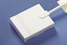
Figure 1. WSP leakage sensor (water sensor passive)
In addition to leakage sensors, the set also includes two (cold and hot water) ball valves with electric drive (SHEP) of the Italian company BUGATTI, control unit, 12 volt battery, 1.3 ampere * hour. Ball valves are available with 1/2, 3/4 and one inch connecting threads. Hence the difference in the purpose and price of the sets. ShEP cranes are available for 12V DC and 220V AC.However, given the requirements of electrical safety, it is better to focus on low-voltage equipment 12-24V.
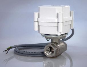
Figure 2. Electric ball valve
So the “APARTMENT 1” set contains 2 half-inch SHEPs, and its cost is 10,000 rubles. "APARTMENT 1" in the same configuration, but with brass SHEP is a little more expensive - 11,600. You can distinguish these sets by name: the first is called ULTIMATE BUGATTI, and the second is PROFESSIONAL BUGATTI.
A set of apartment 3 with a 1-inch ShEP is already 12,400 rubles. The price is somewhere on the level of an inexpensive laptop or tablet, it seems to be expensive. But compared to the renovation of the neighbors on the lower floor - not so much. Over time, prices can change, of course, upward.
If the ready-made kit for some reason does not fit, for example, there are not enough sensors, you can always buy any missing item at retail. The company also provides such a service.
Sensors with WSR (water sensor radio)
One of the GIDROLOCK innovations is leakage sensors with a radio channel. Such sensors can be connected to control units of the latest models: GIDROLOCK CONTROL, GIDROLOCK PREMIUM, GIDROLOCK UNIVERSAL, etc. The use of sensors with a radio channel is justified when used in water supply, heating or sewage systems, when the use of conventional wired sensors is impossible or difficult: the distant location of the sensors or the reluctance to hammer walls for laying communication lines.
In case of water ingress on the sensor electrodes, the latter transmits an alarm event signal to the receiver connected to the control unit. The transmission of the alarm signal continues until a response from the receiver is received (transmission according to the “request-response” principle). The result of such a radio exchange is the closure of the corresponding SHEP.
The sensors themselves are a large tablet with a diameter of 50 and a height of 12 mm. The range of within line of sight is at least 500 m, powered by a built-in battery, the life of which the manufacturer guarantees for as long as 24 years. Sensors are operable in the temperature range of -20 - +60 degrees. Much better!

Figure 3. WSR Sensor
WSR sensors are available in various colors, which can be specified when ordering, including those with a pattern matching the color of linoleum or tile. The base color of the sensors is white. And if radio sensors are used, then you can’t do without a remote control at all. And such a remote control is also there. Its range is 250 m, the service life of the built-in battery is 7 years: at any time you can close or open the power supply, stop the flow of water in an emergency or just in case of repair, for example, a separate tap or mixer.
One could find a sufficient number of industrial-made devices for signaling water leaks, and it turns out that they are no worse, or maybe even better, than GIDROLOCK systems, so this article can in no way be regarded as advertising products of this particular company. Just this system is taken as an example to show the nature and breadth of the flooding problem and how to solve it.
In addition to the Hydrolock system, online stores and firms also offer Neptune, Aquastorozh, Rainbow, Aquasensor, Adlan-T and others. Which of these systems to use can only be decided on an individual basis by comparing its properties, price and its financial capabilities. But with the current level of electronics, imported components, as well as competition between firms, all systems are most likely quite reliable and functional in their properties.
Leakage sensors such as WSP and WSR are point sensors, therefore, they only detect leakage when water reaches them. Other systems use sensors based on an SC sensor cable. Such a cable can be easily laid around the perimeter of the room, placed with a snake over the entire area of the room, or in some other way.
SC cable is fastened to the floor surface using plastic clips with a self-adhesive base, or “earring” type clips with screws. In general, when using an SC cable, the exclusion of blind spots is guaranteed.
For use with the SC cable, the LDM 0.5 control unit is used. Connecting the cable is quite simple: according to the instructions of the wire of four colors, connect to the terminals with the corresponding numbers. Based on the sensor cable, for example, the Rainbow system mentioned above is working.
You can read more about using the SC sensor cable in its technical passport, which can be found on any Internet search engine. There is also a connection diagram and drawings with schemes for laying the cable in the room.
Needless to say, industrial manufacturing systems are certainly good, but the average consumer is somewhat confused by the price of the issue. In addition, if this ordinary consumer is also a radio amateur, then assembling such a device from illiquid parts will not be difficult. True, it is unlikely that you will get a super appliance that turns off the water during an accident, but in some cases it can quite adequately cope with the task, a simple sound alarm, assembled from several parts. Next, we will consider several schemes that were developed by radio amateurs at different times, there should be still Soviet time.
Simple home-made circuits for detecting water leaks
Here it is time to recall another proverb: "Everything ingenious is simple." This is how you can characterize the circuit shown in the figure below. The most appropriate name for it is “The simplest leak detector.”
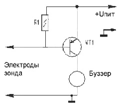
Figure 4. The simplest sensor
The circuit is so simple, contains only three details, that anyone who picks up a soldering iron for the first time in his life can assemble it on his own. Most likely, not everything will turn out right away: the soldering iron overheats, the solders turn out dull and loose, the findings of the parts and wires are not tinned.
In addition, it is not clear why the transistor has three legs, and where to solder them. All this will make you turn to the relevant literature or just ask friends of the radio amateur. But, if all the obstacles are overcome, the scheme works, and it will be by all means, then it may happen that the ranks of ham radioists replenish with another person. This happens often when the assembled design produced the expected results.
For the manufacture of the circuit, you need any low-power p-n-p transistor. It can be KT361, KT502, KT209 and any similar. Resistor R1 has a nominal value of 10 - 20 kOhm. Its purpose is to keep the transistor closed. To generate an audio signal, a buzzer is used (buzzer - literal translation of a buzzer, a sound alarm device, "tweeter") with a built-in generator. But everywhere it is called the buzzer in the English manner, so you have to adhere to tradition.
Such a buzzer starts emitting sound with a frequency of about 2KHz, as soon as a supply voltage is applied to it. Buzzers are available for voltage of 1.5 - 12V. In this design, it is suitable with a voltage of 9 - 12V. The "positive" output of the buzzer is connected to the collector of the transistor VT1.
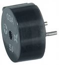
Figure 5. Buzzer
The probe probe is made in the form of a plate of foil fiberglass with dimensions of 20 * 60 mm. To obtain two electrodes, it is enough to cut the foil on the plate with a cutter from a hacksaw blade. It is advisable to irradiate the obtained strips, rinse the remaining flux with alcohol. You can also simply lay two electrodes on the floor next to it, preferably stainless steel wire. Ordinary knitting needles are quite suitable for these purposes.
The design of the sensor is so simple that you do not need to reinvent the circuit board, everything can be assembled by wall mounting. You don’t even need a power switch: in standby mode, the transistor is closed and almost nothing is consumed from the battery.
As a battery, “Krona” is used, or rather its modern imported counterpart. Although such batteries are quite durable, they can be stored for several years, nevertheless, the battery condition must be checked periodically. The easiest way to do this is by bridging the probe electrodes with at least a damp cloth or even a finger. The probe should not be short-circuited, as the transistor may fail.
The sensor works like this. When liquid enters the probe electrodes, its resistance decreases to several kilo-ohms, which causes the transistor to open. Through an open transistor, the supply voltage is supplied to the buzzer and an audible signal is heard.
To detect leaks, sensors, several can be laid out on the floor in the alleged places of water leakage. The sensors are fastened with adhesive tape or tape. In addition, each sensor is powered, of course, from its own separate battery.
The “Sound Leakage Alarm” circuit shown in the following figure is slightly more complicated. Its meaning is the same as that of a circuit on a single transistor, only a little more details and there is the possibility of adjusting the sensitivity.
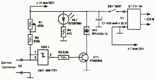
Figure 6. Sound leak detector
Its basis is a threshold element on the K561TL1 chip, which includes 4 two-input Schmitt trigger. In this scheme, only one element is used. The inputs of the remaining three unused elements should be connected to a common wire. This will reduce the total current consumption and protect the outputs of the chip from breakdown. The threshold voltage is shown in the following figure.
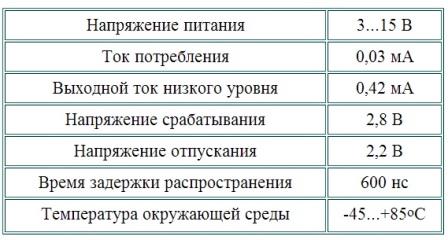
Figure 7. Technical data of the K561TL1 chip
When the microcircuit is turned on, as shown in the figure, a Schmitt trigger with one input and one output is obtained. The logic of this element is extremely simple. When the input voltage exceeds the trip voltage of 2.8 V, the output is set to logic zero. In this case, the transistor VT1 is closed, so the buzzer is silent.
If the input voltage at terminals 1,2 is reduced even very slowly and smoothly, then when it is reduced to 2.2V, the output of the DD1.1 element will quickly and sharply display the level of a logical unit that will open the transistor VT1 and an audio signal will sound. Despite the relatively small size of the buzzer, its sound, as a rule, is very loud and nasty, it is simply impossible not to hear.
The input voltage is generated by a divider formed by a chain of resistors R1, R2 and a leakage sensor, the design of which was described just above. It is easy to calculate that at the resistors indicated in the diagram, a decrease in the sensor resistance to 50 - 100KΩ will lead to a "drawdown" in the voltage at the input of the Schmitt trigger below 2.2V. If the sensor is dry, almost “open”, the input voltage is almost equal to the supply voltage.
The alarm is powered by power supply unit for voltage 9 - 12V. Any network adapter or power supply unit from Polish "antenna dryers" is quite suitable for these purposes.
The presence of the supply voltage is monitored using the HL1 LED, which consumes the majority of the power while the indicator is in standby mode. Therefore, if the device is supposed to be powered by a battery, this LED should be excluded from the circuit.
Such amazing simplicity of the above schemes is due to the use of a buzzer with an integrated generator in them: they supplied power and, please, squeaked. If you use a conventional piezo emitter or a dynamic head, then the circuit looks a little different. The flooding sensor turns on the generator, and already it produces sound vibrations.
Below is a diagram using a generator based on integrated timer NE555.
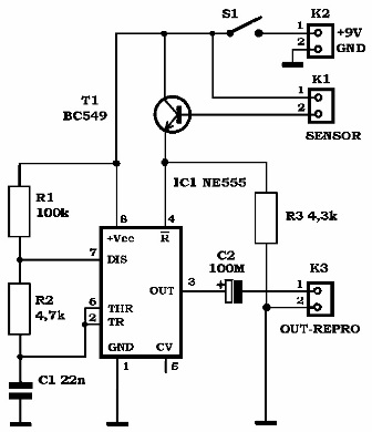
Figure 8. Scheme of the leak detector on the 555 timer
In fact, this circuit differs little from the circuit on a single transistor, discussed above. The leakage sensor, the same two strips of fiberglass or two knitting needles, is connected to the base of transistor T1.When the sensor is wetted, its resistance decreases and transistor T1 opens. The current through the collector-emitter junction creates a voltage drop on resistor R3, which is applied to pin 4 of NE555.
Pin 4 is the input / R (reset) of the NE555 timer. Logical zero at this input prohibits, stops the operation of the entire microcircuit, so the generator is silent, and at pin 3 there is a logic zero level. The voltage drop across the resistor R3 is perceived by the timer as a logical unit. Therefore, the generator starts, at the output 3, rectangular pulses of sound frequency appear. The generator itself is made according to the standard scheme, a description of which can be found in the article on the NE555 timer.
The output stage of the NE555 chip is quite powerful, therefore, to obtain an audio signal, you can directly connect an electromagnetic emitter with a winding resistance of at least 50 Ohms to the circuit output.
There are many similar simple schemes. They are most often performed on transistors or microcircuits of a small degree of integration, as a rule, K561. But with some differences in the circuits, the principle of operation is the same: water leaked, the sensor got wet, the generator turned on, a sound came out. Therefore, to understand the principle of operation of such leakage detectors, the three considered schemes are sufficient.
New elemental base - new circuits, new opportunities
But radio amateurs are creative and restless people. In the era of microcontrollers, leak sensors are created precisely on them. The principle of operation is approximately the same as described above, only the reaction of smart circuits to leakage can be more diverse. For example, when the sensor is slightly humidified, the device starts to make short rare beeps. As the water level rises, the beeps begin to become more frequent, change their tone, or turn into a solid sound signal.
A similar system may also have intermediate relaywhose contacts connected to security alarm or to electrified faucets such as SHEP, blocking the water at the right time. It turns out the system is no worse than the industrial ones described above.
Based on the modern elemental base, it is quite easy to create leakage sensors operating over the air. To do this, it is enough to combine a microcontroller and a radio signal transmission module in one design. And such schemes in the arsenal of amateur designs already exist.
To change abilities microcontroller systemIt’s not at all necessary to change something in the circuit using a soldering iron and a screwdriver. The necessary parameters are easily achieved by simply changing the microcontroller program.
Boris Aladyshkin
P.S. Addition to the article. An example of a graphic drawing of how leakage sensors can be used in some arbitrary plumbing room.
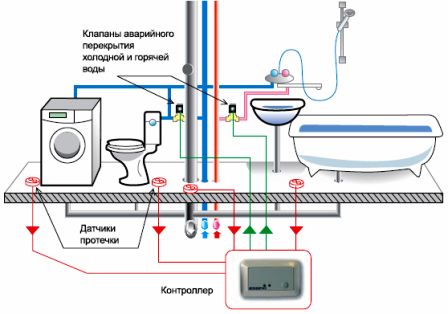
Note. Everything can change when using another type of equipment. You should always take into account the technical conditions of your plumbing unit (the location of the pipes for water supply, as well as the location of other types of plumbing products - sinks, bathtubs, toilets, etc.).
See also at bgv.electricianexp.com
:
