Categories: Novice electricians, Electric motors and their application
Number of views: 93951
Comments on the article: 3
Squirrel cage and phase rotor - what is the difference
As you know, induction motors have a three-phase winding (three separate windings) of the stator, which can form a different number of pairs of magnetic poles depending on their design, which in turn affects the rated engine speed at the rated frequency of the supplying three-phase voltage. At the same time, the rotors of this type of motor may differ, and for asynchronous motors they are short-circuited or phase. What distinguishes a squirrel-cage rotor from a phase rotor - this will be discussed in this article.
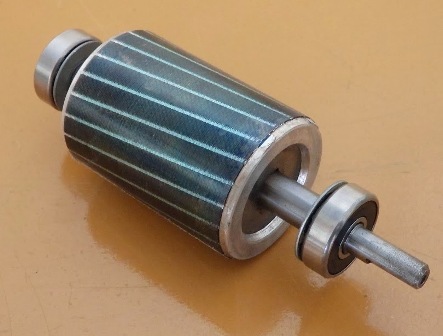
Squirrel cage rotor
Ideas about the phenomenon of electromagnetic induction will tell us what will happen with a closed coil of a conductor placed in a rotating magnetic field, similar to the magnetic field of a stator of an induction motor. If such a coil is placed inside the stator, then when a current is supplied to the stator winding, EMF will be induced in the coil and a current will appear, that is, the picture will take the form: magnetic current loop. Then a pair of Ampere forces will act on such a coil (closed loop), and the coil will begin to turn after the movement of the magnetic flux.
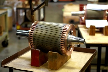
This is how an asynchronous motor with a squirrel-cage rotor works, only instead of a turn on its rotor are copper or aluminum rods, short-circuited between themselves by rings from the ends of the rotor core. A rotor with such short-circuited rods is called a squirrel-cage or “squirrel cage” type rotor because the rods located on the rotor resemble a squirrel wheel.
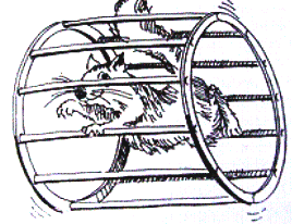
The alternating current passing through the stator windings, generating a rotating magnetic field, induces current in closed circuits of the “squirrel cage”, and the entire rotor comes into rotation, because at each moment of time different pairs of rotor rods will have different induced currents: some rods are large currents, some - smaller, depending on the position of certain rods relative to the field. And the moments will never balance the rotor, which is why it will rotate while alternating current flows through the stator windings.
Moreover, the squirrel cage rods are slightly inclined with respect to the axis of rotation - they are not parallel to the shaft. The inclination is made so that the rotation moment is kept constant and does not pulsate, in addition, the inclination of the rods allows to reduce the effect of higher harmonics induced in the EMF rods. If the rods were not tilted, the magnetic field in the rotor would pulsate.
Glide s
Asynchronous motors are always characterized by slip s, which occurs due to the fact that the synchronous frequency of the rotating magnetic field n1 of the stator is higher than the real rotational speed of the rotor n2.
Sliding occurs because the emf induced in the rods can take place only when the rods move relative to the magnetic field, that is, the rotor is always forced to at least slightly, but lag behind the stator magnetic field in speed. The amount of slip is s = (n1-n2) / n1.
If the rotor rotated with the synchronous frequency of the stator magnetic field, then no current would be induced in the rotor rods, and the rotor would simply not rotate. Therefore, the rotor in an induction motor never reaches the synchronous frequency of rotation of the stator magnetic field, and always at least slightly (even if the load on the shaft is critically small), but lags behind the frequency of rotation from the synchronous frequency.
Slip s is measured in percent, and at idle it almost approaches 0, when the moment of counteraction from the side of the rotor is almost absent. In the event of a short circuit (rotor is locked), the slip is 1.
In general, slip for squirrel-cage induction motors depends on the load and is measured in percent. Nominal slip is slip at a nominal mechanical load on the shaft under conditions where the supply voltage corresponds to the motor rating.
Other articles on squirrel cage induction motors at i.electricianexp.com:
Single phase induction motor device
Connection of a three-phase motor to a single-phase network
How to check the electric motor
Phase rotor
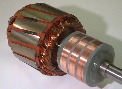
Phase rotor induction motors, unlike squirrel-cage induction motors, have a full three-phase winding on the rotor. Just as a three-phase winding is laid on a stator, a three-phase winding is laid in the grooves of a phase rotor.
The terminals of the phase rotor winding are connected to slip rings mounted on the shaft and insulated from each other and from the shaft. The winding of the phase rotor consists of three parts - each for its own phase - which are most often connected according to the "star" scheme.
An adjusting rheostat is connected to the winding of the rotor through contact rings and brushes. Cranes and elevators, for example, are launched under load, and here it is necessary to develop a significant working moment. Despite the complexity of the design, asynchronous motors with a phase rotor have better adjusting capabilities regarding the working moment on the shaft than asynchronous motors with a squirrel-cage rotor, which require industrial frequency converter.
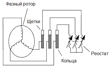
The stator winding of an asynchronous motor with a phase rotor is carried out in the same way as on the stators of asynchronous motors with a squirrel-cage rotor, and in a similar way creates, depending on the number of coils (three, six, nine or more coils), two, etc. poles. The stator coils are shifted among themselves by 120, 60, 40, etc. degrees. At the same time, as many poles are made on the phase rotor as on the stator.
By adjusting the current in the rotor windings, the operating torque of the motor and the amount of slip are regulated. When the adjusting rheostat is fully withdrawn, then to reduce the wear of the brushes and rings they are short-circuited using a special device for lifting the brushes.
See also: How is the transformer arranged
See also at i.electricianexp.com
:
