Categories: Novice electricians, Electric motors and their application
Number of views: 143417
Comments on the article: 1
How to check the status of the winding of an electric motor
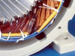 At first glance, the winding is a piece of wire wound in a certain way and there is nothing much to break in it. But she has features:
-
strict selection of homogeneous material along the entire length;
-
accurate calibration of shape and cross section;
-
application at the factory a layer of varnish with high insulating properties;
-
strong contact connections.
If at any point in the wire any of these requirements is violated, the conditions for the passage of electric current change and the engine starts to work with reduced power or stops altogether.
To test one winding of a three-phase motor, disconnect it from other circuits. In all electric motors, they can be assembled according to one of two schemes:
1. stars;
2. The triangle.
The ends of the windings are usually output to the terminal blocks and are marked with the letters "H" (beginning) and "K" (end). Sometimes individual connections can be hidden inside the case, and other methods of designation, for example, with numbers, are used for conclusions.
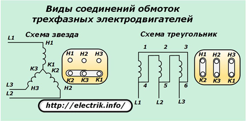
In a three-phase motor on the stator, windings with the same electrical characteristics and equal resistances are used. If at measurement with an ohmmeter If they show different values, then this is an occasion to seriously think about the reasons for the dispersion of evidence.
How are faults in the winding
Visually assessing the quality of the windings is not possible due to the limited access to them. In practice, their electrical characteristics are checked, given that all faults in the windings are manifested:
-
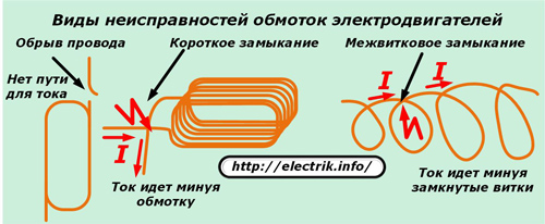
a cliff when the integrity of the wire is violated and the passage of electric current through it is excluded;
-
a short circuit that occurs when the insulation layer is broken between the input and output turns, characterized by the exclusion of the winding from work with shunting of the ends;
-
inter-turn closure, when the insulation is broken between one or more closely spaced turns, which are thus taken out of operation. The current flows through the winding, bypassing the short-circuited turns, not overcoming their electrical resistance and not creating a certain work for them;
-
breakdown of insulation between the winding and the housing of the stator or rotor.
Checking the winding for wire breaks
This type of malfunction is determined by measuring the insulation resistance with an ohmmeter. The device will show a large resistance - ∞, which takes into account the gap formed by the gap in the airspace.
Checking winding for short circuit
The engine, inside the electrical circuit of which there is a short circuit, is switched off by the mains protection. But, even with a quick decommissioning in this way, the place where the short-circuit occurs is clearly visible visually due to the effects of high temperatures with pronounced soot or traces of metal fusion.
With electrical methods for determining the winding resistance with an ohmmeter, a very small value is obtained, very close to zero. Indeed, almost the entire length of the wire is excluded from measurement due to accidental shunting of the input ends.
Checking the winding for interturn circuit
This is the most hidden and difficult to identify fault. To identify it, you can use several methods.
Ohmmeter method
The device operates on direct current and measures only the active resistance of the conductor. The winding during operation due to the turns creates a significantly larger inductive component.
When one coil is closed, and their total number can be several hundred, it is very difficult to notice a change in active resistance.After all, it varies within a few percent of the total value, and sometimes even less.
You can try to accurately calibrate the device and carefully measure the resistance of all windings, comparing the results. But the difference in readings even in this case will not always be visible.
More accurate results can be obtained by the bridge method of measuring the active resistance, but this is usually a laboratory method, inaccessible to most electricians.
Measurement of consumption currents in phases
With inter-turn circuit, the ratio of currents in the windings changes, excessive stator heating manifests itself. A working motor has the same currents. Therefore, their direct measurement in the current circuit under load most accurately reflects the real picture of the technical condition.
AC measurements
It is not always possible to determine the total resistance of the winding, taking into account the inductive component in the full working circuit. To do this, you will have to remove the cover from the terminal box and crash into the wiring.
In a deactivated engine, a step-down transformer with a voltmeter and ammeter can be used for measurement. To limit the current will allow a current-limiting resistor or a rheostat of the corresponding rating.
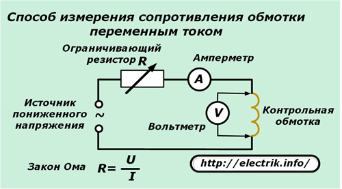
When measuring, the winding is inside the magnetic circuit, and the rotor or stator can be removed. There will be no balance of electromagnetic flows, on the condition of which the engine is designed. Therefore, a low voltage is used and currents are controlled that must not exceed the rated values.
The voltage drop measured on the winding divided by the current, according to Ohm's law, will give the impedance value. It remains to be compared with the characteristics of other windings.
The same scheme allows you to remove the current-voltage characteristics of the windings. You just need to take measurements on different currents and write them in a tabular form or build graphs. If, when comparing with similar windings, there are no serious deviations, then there is no interturn closure.
Ball in stator
The method is based on the creation of a rotating electromagnetic field with serviceable windings. For this, a three-phase symmetrical voltage is applied to them, but always of a reduced value. For this purpose, three identical step-down transformers operating in each phase of the power circuit are usually used.
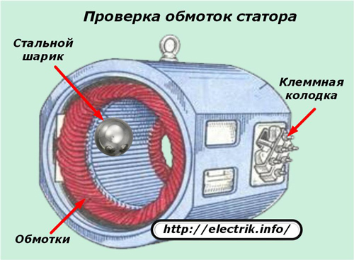
To limit the current loads on the windings, the experiment is carried out briefly.
A small steel ball from the ball bearing is introduced into the rotating magnetic field of the stator immediately after turning on the coils under voltage. If the windings are serviceable, then the ball simultaneously rolls along the inner surface of the magnetic circuit.
When one of the windings has an interturn circuit, the ball will freeze at the fault location.
During the test, it is impossible to exceed the current in the windings greater than the nominal value and it should be borne in mind that the ball freely jumps out of the housing with a speed of departure from the slingshot.
Electrical check of the polarity of the windings
In stator windings, there may be no marking of the beginning and ends of the conclusions and this will complicate the correct assembly.
In practice, 2 methods are used to search for polarity:
1. using a low-power constant current source and a sensitive ammeter, showing the direction of the current;
2. using a step-down transformer and voltmeter.
In both versions, the stator is considered as a magnetic circuit with windings, operating by analogy with a voltage transformer.
Polarity check with battery and ammeter
On the outer surface of the stator, three separate windings are drawn by six wires, the beginnings and ends of which must be determined.
Using an ohmmeter, the outputs related to each winding are called up and marked, for example, with the numbers 1, 2, 3. Then, the beginning and end are randomly marked on any of the windings. To one of the remaining windings connect an ammeter with an arrow in the middle of the scale, capable of indicating the direction of the current.
The minus of the battery is rigidly connected to the end of the selected winding, and the plus is briefly touched to its beginning and immediately break the circuit.
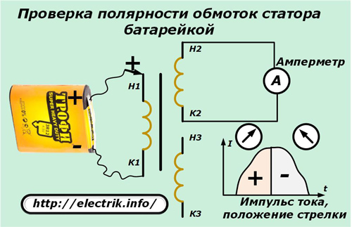
When a current pulse is supplied to the first winding, it is transformed into a second circuit closed through an ammeter due to electromagnetic induction, repeating the original form. Moreover, if the polarity of the windings is correctly guessed, the arrow of the ammeter will deviate to the right at the beginning of the pulse and move to the left when the circuit is opened.
If the arrow behaves differently, then the polarity is simply confused. It remains only to mark the conclusions of the second winding.
The next third winding is checked in the same way.
Polarity check with step-down transformer and voltmeter
Here, too, the windings are first called up with an ohmmeter, determining the conclusions that relate to them.
Then the ends of the first selected winding are randomly marked for connection to a step-down voltage transformer, for example, 12 volts.
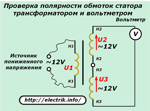
The two remaining windings are randomly twisted at one point by two leads, and the remaining pair is connected to a voltmeter and supplies power to the transformer. Its output voltage is transformed into the remaining windings with the same magnitude, since they have an equal number of turns.
Due to the serial connection of the second and third windings, the voltage vectors will add up, and their sum will be shown by a voltmeter. In our case, when the direction of the windings coincides, this value will be 24 volts, and with different polarity - 0.
It remains to mark all the ends and carry out a control measurement.
The article gives a general procedure for checking the technical condition of some arbitrary engine without specific technical characteristics. They can change in each individual case. See them in the documentation for your equipment.
See also at bgv.electricianexp.com
:
