Categories: Featured Articles » Novice electricians
Number of views: 12986
Comments on the article: 0
Principles of electric motor for dummies
The basis of the electric motor, both direct current and alternating current, is based on Ampere force. If you do not smother how it turns out, then nothing will ever be incomprehensible.
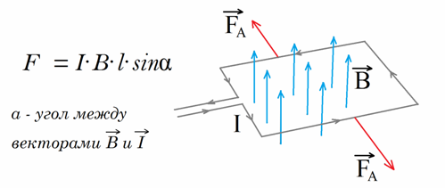
Fig. 1
P.S. In fact, there is a vector product and differentials, but these are details, and we have a simplified, special case.
The direction of the ampere force is determined by the rule of the left hand.
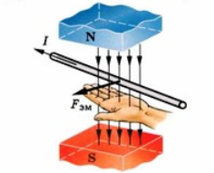
Fig.2
Mentally put the left palm on the upper figure and get the direction of Ampere forces. She type stretch the frame with the current in that position as shown in Fig. 1. And nothing will turn around here, the frame is in balance, stable.
And if the frame with the current is rotated differently, then this is what will happen:
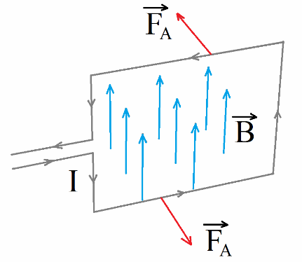
Fig.3
There is no equilibrium here already, the Ampere force unfolds the opposite walls so that the frame begins to rotate. Mechanical rotation appears. This is the basis of the electric motor, the very essence, then only the details.
Further.
Now what will the frame with current in Fig. 3 do ?. If the system is perfect, without friction, then obviously there will be oscillations. If friction is present, then the oscillations gradually damp, the frame with current stabilizes and becomes as in Fig. 1.
But we need constant rotation and it can be achieved in two fundamentally different ways, and from here the difference arises between DC and electric motors.
Method 1. Change the direction of the current in the frame.
This method is used in DC motors and its descendants.
We are watching the pictures. Let our engine be de-energized and the frame with the current oriented somehow randomly, like this for example:
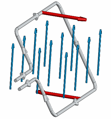
Fig. 4.1 Randomly positioned frame
Ampere force acts on a randomly located frame and it starts to rotate.
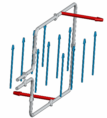
Figure 4.2
During movement, the frame reaches an angle of 90 °. The moment (moment of a pair of forces or rotational moment) is maximum.
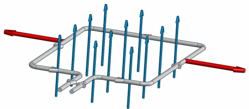
Figure 4.3
And now the frame reaches a position when there is no moment of rotation. And if you do not turn off the current now, the Ampere force will already slow down the frame and at the end of a half-turn the frame will stop and begin to rotate in the opposite direction. But we don’t need it.
Therefore, we make a tricky move in Fig. 3 - we change the direction of the current in the frame.
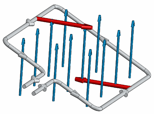
Fig.4.4
And after crossing this position, the frame with the changed current direction is no longer braked, but accelerates again.
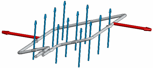
Fig.4.5
And when the frame approaches the next equilibrium position, we change the current again.
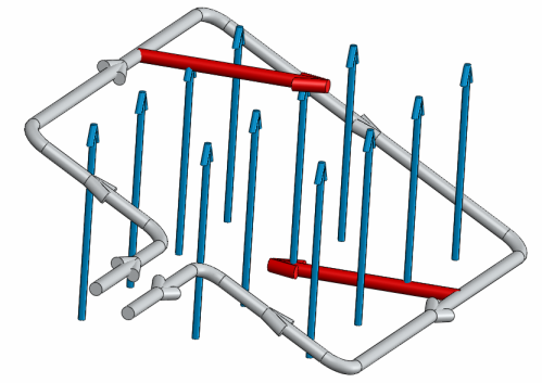
Fig.4.6
And the frame again continues to accelerate where we need to.
And so it turns out a constant rotation. Handsomely? Handsomely. It is only necessary to change the direction of the current two times per revolution and the whole business.
And he does it, i.e. provides a change of current special unit - brush-collector unit. In principle, it is organized as follows:
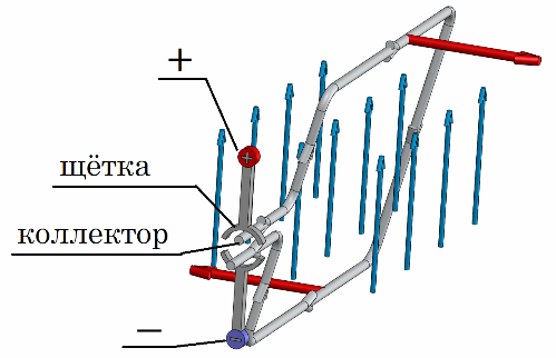
Fig.5
The figure is clear and without explanation. The frame rubs on one contact, then on another, and so the current changes.
A very important feature of the brush-collector unit is its small resource. Due to friction. For example, here is the DPR-52-N1 engine - the minimum operating time of 1000 hours. At the same time, the service life of modern brushless motors is more than 10,000 hours, and AC motors (there are also no SHKU) there are more than 40,000 hours.
P.S. In addition to the standard DC motor (standard, this means with a brush-collector unit), there is also its development: a brushless DC motor (BDT) and a valve motor.
BDTT differs in that the current there changes electronically (transistors close and open), and the valve is even steeper, it also changes the current, controlling the moment. In general, BDTTs with a valve in complexity are comparable to an electric drive, because they have all kinds of rotor position sensors (Hall sensors for example) and a complex electronic controller.
The difference between the BDTT and the valve motor in the form of counter-EMF. In the BDT there is a trapezoid (a gross change), and in a valve motor - a sinusoid, a smoother means.
In English, BDT is BLDC, and the valve motor is PMSM.
Method 2. The magnetic flux is rotated, i.e. a magnetic field.
A rotating magnetic field is obtained using an alternating three-phase current. There is a stator.
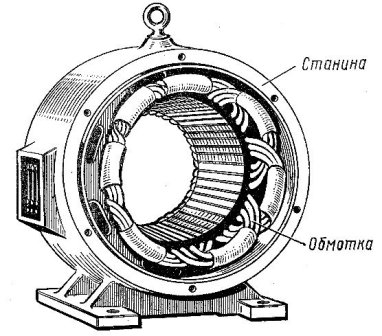
Fig.6
And there are 3 phases of alternating current.
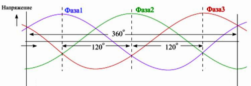
Fig. 7
Between them, apparently 120 degrees, electrical degrees.
These three phases are placed in the stator in a special way so that they are geometrically rotated 120 ° towards each other.
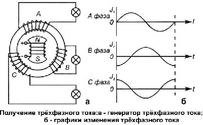
Fig. 8
And then when three-phase power is applied, a rotating magnetic field is obtained by folding magnetic fluxes from the three windings.
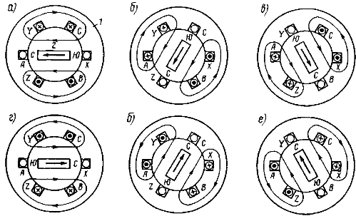
Fig. 9
Next, the rotating magnetic field “presses” the Ampere force on our frame and it rotates.
But there are also differences, two different ways.
Method 2a. The frame is powered (synchronous motor).
We give means to the frame voltage (constant), the frame is exposed to the magnetic field. Remember fig. 1 from the beginning? This is how the frame becomes.
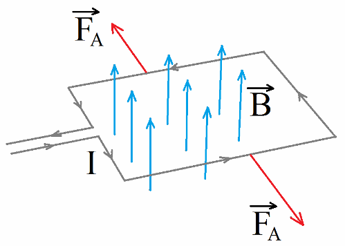
Fig. 10 (Fig. 1)
But the magnetic field here is spinning, and not just hanging. What will the frame do? It will also rotate, following the magnetic field.
They (the frame and the field) rotate with the same frequency, or synchronously, so these motors are called synchronous motors.
Method 2b. The frame is not powered (asynchronous motor).
The trick is that the frame does not feed, does not feed at all. Just a wire so closed.
When we begin to rotate the magnetic field, according to the laws of electromagnetism, a current is induced in the frame. Ampere force is obtained from this current and magnetic field. But Ampere’s force will arise only if the frame moves relative to the magnetic field (a well-known story with Ampere’s experiments and his trips to the next room).
So the frame will always lag behind the magnetic field. And then, if for some reason she suddenly catches up with him, then the tip from the field will disappear, the current will disappear, the Ampere force will disappear and everything will disappear altogether. That is, in an induction motor the frame always lags behind the field and their frequency means different, that is, they rotate asynchronously, therefore the motor is called asynchronous.
See also on this topic: How are single-phase asynchronous motors arranged and working?, Types of electric generators, device and their operation
See also at bgv.electricianexp.com
:
