Categories: Novice electricians, How does it work, Industrial electrician
Number of views: 15652
Comments on the article: 1
How is the transformer arranged and working, what characteristics are taken into account during operation
In energy, electronics and other branches of applied electrical engineering, a large role is given to transformations of electromagnetic energy from one type to another. Numerous transformer devices, which are created for various production tasks, deal with this issue.
Some of them, having the most complex design, perform the transformation of powerful high-voltage energy flows, for example. 500 or 750 kilovolts in 330 and 110 kV or in the opposite direction.
Others work as a part of small-sized devices of household appliances, electronic devices, automation systems. They are also widely used. in various power supplies of mobile devices.
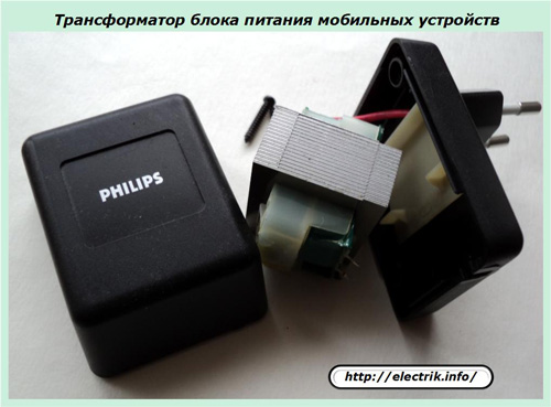
Transformers operate only in AC circuits of different frequencies and are not intended for use in DC circuits that use other types of converters.
Transformers are divided into two main groups: single-phase, powered by a single-phase alternating current network, and three-phase, powered by a three-phase alternating current network.
Transformers are very diverse in design. The main elements of the transformer are: a closed steel core (magnetic core), windings and parts used for fastening the magnetic circuit and coils with windings and installing the transformer in the rectifier device. The core pipe is designed to create a closed path for magnetic flux.
The parts of the magnetic circuit on which the windings are located are called rods, and the parts on which there are no windings and which serve to close the magnetic flux in the magnetic circuit are called yokes. The material for the transformer magnetic circuit is sheet electrical steel (transformer steel). This steel can be of various grades, thicknesses, hot and cold rolling.
General principles of operation of transformers
We know that electromagnetic energy is inextricable. But it is customary to represent it in two components:
1. electrical;
2. magnetic.
It’s easier to understand the phenomena that occur, describe processes, make calculations, design various devices and circuits. Entire sections of electrical engineering are devoted to separate analyzes of the operation of electrical and magnetic circuits.
Electric current, like magnetic flux, flows only along a closed circuit with resistance (electric or magnetic). It is created by external applied forces - voltage sources of the corresponding energies.
However, when considering the operating principles of transformer devices, it will be necessary to simultaneously study both of these factors and take into account their complex effect on power conversion.
The simplest transformer consists of two windings made by winding coils of an insulated wire through which electric current flows and one line for magnetic flux. It is commonly called a core or magnetic core.
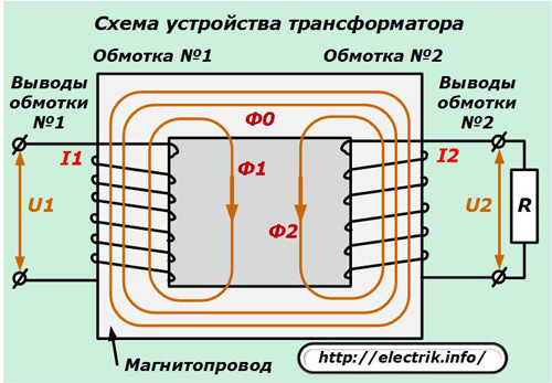
The voltage from the electric power source U1 is applied to the input of one winding, and from the terminals of the second it, after conversion to U2, is supplied to the connected load R.
Under the action of voltage U1 in the first winding, a current I1 flows through a closed circuit, the value of which depends on the impedance Z, which consists of two components:
1. active resistance of the wires of the winding;
2. reactive component with an inductive character.
The magnitude of the inductance has a great influence on the operation of the transformer.
The electric energy flowing through the primary winding in the form of current I1 is a part of electromagnetic energy, the magnetic field of which is directed perpendicular to the movement of charges or the location of the turns of wire. The transformer core is located in its plane - the magnetic circuit, through which the magnetic flux F.
All this is clearly reflected in the picture and is strictly observed during manufacture. The magnetic circuit itself is also closed, although for certain purposes, for example, to reduce the magnetic flux, gaps can be made in it, increasing its magnetic resistance.
Due to the flow of the primary current through the winding, the magnetic component of the electromagnetic field penetrates the magnetic circuit and circulates through it, crossing the turns of the secondary winding, which is closed to the output resistance R.
Under the influence of magnetic flux, an electric current I2 is induced in the secondary winding. Its value is affected by the value of the applied magnetic component strength and the impedance of the circuit, including the connected load R.
When the transformer is operating inside the magnetic circuit, a common magnetic flux F and its components F1 and F2 are created.
How the autotransformer is arranged and works
Among transformer devices, simplified constructions are especially popular, using not two different separately made windings, but one common, divided into sections. They are called autotransformers.
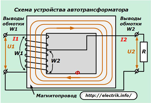
The principle of operation of such a circuit has practically remained the same: the input electromagnetic energy is converted to output. Primary currents I1 flow through the windings of the winding W1, and secondary I2 flow through W2. The magnetic circuit provides a path for magnetic flux F.
The autotransformer has a galvanic connection between the input and output circuits. Since not all the applied power of the source is converted, but only part of it, a higher efficiency is created than with a conventional transformer.
Such designs can save on materials: steel for the magnetic circuit, copper for windings. They have less weight and cost. Therefore, they are effectively used in the energy system from 110 kV and above.
There are practically no special differences in the operating modes of the transformer and autotransformer.
Transformer Operating Modes
During operation, any transformer can be in one of the following states:
-
out of work;
-
rated mode;
-
idling;
-
short circuit;
-
overvoltage.
Shutdown Mode
To create it, it is enough to remove the supply voltage of the electric power source from the primary winding and thereby exclude the passage of electric current through it, which they always do without fail with similar devices.
However, in practice, when working with complex transformer structures, this measure does not fully provide safety measures: voltage can remain on the windings and cause harm to the equipment, endanger personnel due to accidental exposure to current discharges.
How can this happen?
For small-sized transformers that operate as a power supply, as shown in the top photo, extraneous voltage will not cause any harm. He simply has nowhere to take from there. And on power equipment it must be taken into account. We will analyze two common causes:
1. connecting an external source of electricity;
2. the effect of induced voltage.
First option
On complex transformers, not one, but several windings are used, which are used in different circuits. All of them must be disconnected voltage.
In addition, at substations operated in an automatic mode without constant operating personnel, additional transformers are connected to the buses of power transformers, providing their own needs of the substation with electric power of 0.4 kV.They are designed to power protections, automation devices, lighting, heating and other purposes.
They are called so - TSN or auxiliary transformers. If the voltage is removed from the input of the power transformer and its secondary circuits are open, and work is carried out on the TSN, then there is a possibility of reverse transformation when the voltage of 220 volts from the low side penetrates to the high one via the connected power buses. Therefore, they must be turned off.
Induced voltage action
If a high-voltage line running under voltage passes near the buses of a disconnected transformer, then the currents flowing through it can induce voltage on the tires. It is necessary to apply measures to remove it.
Rated operating mode
This is the normal state of the transformer during its operation for which it was created. The currents in the windings and the voltages applied to them correspond to the calculated values.
The transformer in nominal load mode consumes and converts capacities corresponding to the design values for the entire resource provided for it.
Idle mode
It is created when voltage is supplied to the transformer from the power source, and the load is disconnected at the terminals of the output winding, that is, the circuit is open. This eliminates the flow of current through the secondary winding.
The transformer in idle mode consumes the lowest possible power, determined by its design features.
Short circuit mode
This is the name of the situation when the load connected to the transformer turns out to be shorted, tightly shunted by chains with very low electrical resistances and the entire power supply of the voltage source acts on it.
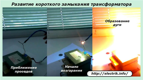
In this mode, the flow of huge short-circuit currents is practically unlimited. They have tremendous thermal energy and are able to burn wires or equipment. Moreover, they act until the power circuit through the secondary or primary winding burns out, breaking in the weakest spot.
This is the most dangerous mode that can occur during the operation of the transformer, and, at any, the most unexpected moment in time. Its appearance can be foreseen, and development should be limited. To this end, they use protections that monitor the excess of permissible currents on the load and turn them off as quickly as possible.
Overvoltage mode
The transformer windings are covered with a layer of insulation, which is created to work under a certain voltage. During operation, it may be exceeded for various reasons that arise both inside the electrical system and as a result of exposure to atmospheric phenomena.
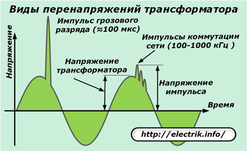
In the factory, the value of the permissible excess voltage is determined, which can act on the insulation for up to several hours and short-term overvoltages created by transients during switching of equipment.
To prevent their impact, they create protection against overvoltage, which, in the event of an emergency, turn off the power from the circuit in automatic mode or limit the discharge pulses.
Continuation of the article:The main types of transformer designs
See also at bgv.electricianexp.com
:
