Categories: How does it work, Electric motors and their application
Number of views: 81554
Comments on the article: 4
Single-phase asynchronous motor: how it works
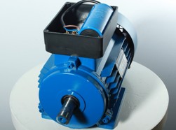 The very name of this electrical device indicates that the electrical energy supplied to it is converted into rotational motion of the rotor. Moreover, the adjective "asynchronous" characterizes the mismatch, the lag of the rotation speed of the armature from the magnetic field of the stator.
The word "single-phase" causes an ambiguous definition. This is due to the fact that the term "phase" in electrics defines several phenomena:
-
shift, difference of angles between vector quantities;
-
potential conductor of two, three or four-wire AC electric circuit;
-
one of the stator or rotor windings of a three-phase motor or generator.
Therefore, we immediately clarify that it is customary to call a single-phase electric motor one that runs on a two-wire AC network represented by a phase and zero potential. The number of windings mounted in various designs of stators does not affect this definition.
Motor design
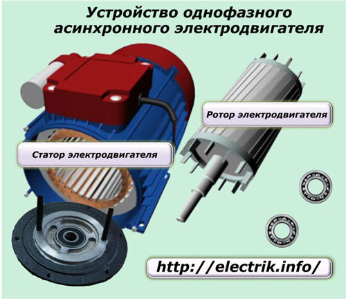
According to its technical device, an induction motor consists of:
1. a stator - a static, fixed part, made by a housing with various electrical elements located on it;
2. a rotor rotated by the forces of the electromagnetic field of the stator.
The mechanical connection of these two parts is made by rotation bearings, the inner rings of which are mounted on the fitted sockets of the rotor shaft, and the outer rings are mounted in protective side covers fixed to the stator.
Rotor
Its device for these models is the same as for all induction motors: a magnetic core from burdened plates based on soft iron alloys is mounted on a steel shaft. On its outer surface, grooves are made into which the winding rods of aluminum or copper are mounted, shorted at the ends to the closing rings.
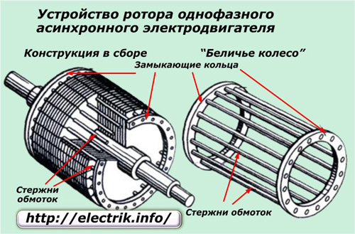
An electric current is induced in the rotor winding, which is induced by the stator magnetic field, and the magnetic circuit serves for the good passage of the magnetic flux created here.
Individual rotor designs for single-phase motors can be made of non-magnetic or ferromagnetic materials in the form of a cylinder.
Stator
The stator design is also presented:
-
body;
-
magnetic circuit;
-
winding.
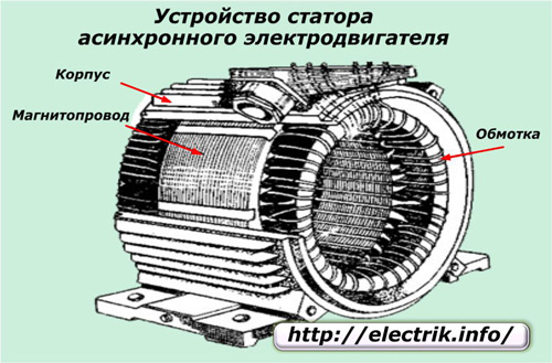
Its main purpose is to generate a fixed or rotating electromagnetic field.
The stator winding usually consists of two circuits:
1. worker;
2. launcher.
In the simplest designs, designed for manual spinning of the anchor, only one winding can be made.
The principle of operation of an asynchronous single-phase electric motor
In order to simplify the presentation of the material, let us imagine that the stator winding is made with only one loop loop. Its wires inside the stator are distributed in a circle at 180 angular degrees. An alternating sinusoidal current passes through it, having positive and negative half-waves. It creates not a rotating, but a pulsating magnetic field.
How magnetic field pulsations occur
Let us analyze this process by the example of the flow of a positive half-wave of current at time instants t1, t2, t3.
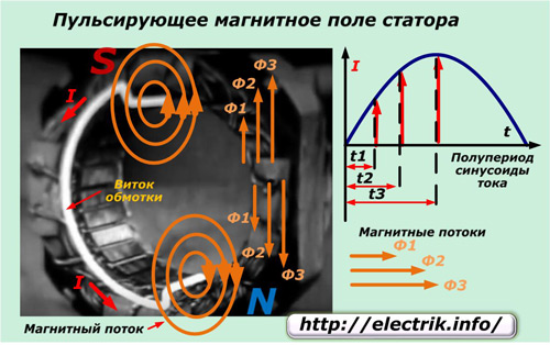
It passes along the upper part of the current path towards us, and along the lower part - from us. In the perpendicular plane represented by the magnetic circuit, magnetic fluxes appear around the conductor.
The currents varying in amplitude at the considered time instants create electromagnetic fields F1, F2, F3 of different magnitude. Since the current in the upper and lower half is the same, but the coil is bent, the magnetic fluxes of each part are directed in the opposite direction and destroy the effect of each other.This can be determined by the rule of a gimlet or right hand.
As you can see, with a positive half-wave, rotation of the magnetic field is not observed, but only its ripple occurs in the upper and lower parts of the wire, which is also mutually balanced in the magnetic circuit. The same process occurs with a negative section of the sinusoid, when the currents reverse direction.
Since there is no rotating magnetic field, the rotor will also remain stationary, because there are no forces applied to it to start rotation.
How rotor rotation is created in a pulsating field
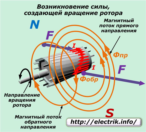
If you give the rotor a rotation, even with your hand, then it will continue this movement. To explain this phenomenon, we show that the total magnetic flux varies in frequency of the current sinusoid from zero to the maximum value in each half-cycle (with a change in direction) and consists of two parts formed in the upper and lower branches, as shown in the figure.
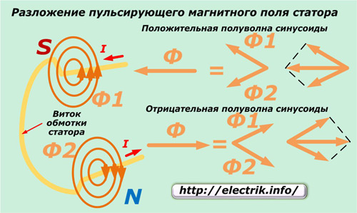
The magnetic pulsating field of the stator consists of two circular ones with an amplitude of Fmax / 2 and moving in opposite directions with the same frequency.
npr = nbr = f60 / p = 1.
In this formula are indicated:
-
npr and nobr frequency of rotation of the magnetic field of the stator in the forward and reverse directions;
-
n1 is the speed of the rotating magnetic flux (r / min);
-
p is the number of pole pairs;
-
f is the frequency of the current in the stator winding.
Now, with your hand, we will give the engine rotation in one direction, and it will immediately pick up the movement due to the occurrence of a torque caused by the sliding of the rotor relative to different magnetic fluxes of the forward and reverse directions.
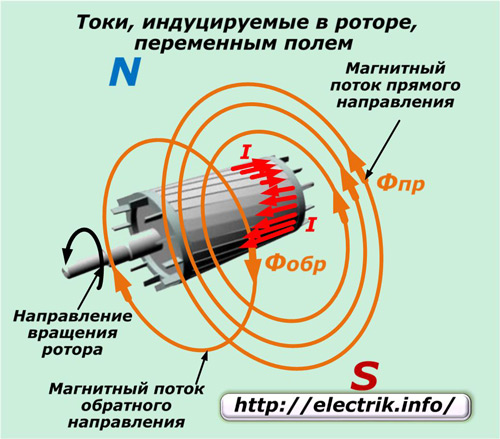
We assume that the magnetic flux of the forward direction coincides with the rotation of the rotor, and the reverse, respectively, will be the opposite. If n2 is the anchor rotation frequency in rpm, then we can write the expression n2 In this case, we denote Spr = (n1-n2) / n1 = S. Here, the indices S and Spr denote the slip of the asynchronous motor and the rotor of the relative magnetic flux of the forward direction. In the reverse flow, the slip Sobr is expressed by a similar formula, but with the change of sign n2. Sobr = (n1 - (-n2)) / n1 = 2-Sbr. In accordance with the law of electromagnetic induction, under the influence of direct and reverse magnetic fluxes, an electromotive force will act in the rotor winding, which will create currents of the same directions I2pr and I2obr in it. Their frequency (in hertz) will be directly proportional to the magnitude of the slip. f2pr = f1 ∙ Spr; f2sample = f1 ∙ S Moreover, the frequency f2obr formed by the induced current I2obr significantly exceeds the frequency f2pr. For example, an electric motor runs on a 50 Hz network with n1 = 1500, and n2 = 1440 rpm. Its rotor has a slip relative to the magnetic flux of the forward direction Spr = 0.04 and the current frequency f2pr = 2 Hz. The reverse slip Sobr = 1.96, and the current frequency f2obr = 98 Hz. Based on the Ampere law, when the current I2pr and the magnetic field Фпр interact, a torque Мпр appears. Mpr = cM ∙ Fpr ∙ I2pr ∙ cosφ2pr. Here, the constant coefficient SM depends on the design of the engine. In this case, the reverse magnetic flux Mobr also acts, which is calculated by the expression: Mobr = cM ∙ Phobr ∙ I2obr ∙ cosφ2obr. As a result of the interaction of these two streams, the resulting one will appear: M = Mpr-Mobr. Attention! When the rotor rotates, currents of different frequencies are induced in it, which create moments of forces in different directions. Therefore, the motor armature will rotate under the action of a pulsating magnetic field in the direction from which it began to rotate. During overcoming of the rated load by a single-phase motor, a small slip is created with the main share of the direct torque Mpr. The counteraction of the inhibitory, reverse magnetic field MOBR has a very slight effect due to the difference in the frequencies of the currents of the forward and reverse directions. f2obr of the reverse current significantly exceeds f2pr, and the induced inductance X2obr greatly exceeds the active component and provides a large demagnetizing effect of the reverse magnetic flux Fobr, which ultimately decreases. Since the power factor of the engine under load is small, the reverse magnetic flux cannot have a strong effect on the rotating rotor. When one phase of the network is applied to a motor with a fixed rotor (n2 = 0), then slip, both forward and reverse, are equal to unity, and magnetic fields and forces of forward and reverse flows are balanced and rotation does not occur. Therefore, from the supply of one phase it is impossible to untwist the motor armature. How to quickly determine the engine speed:
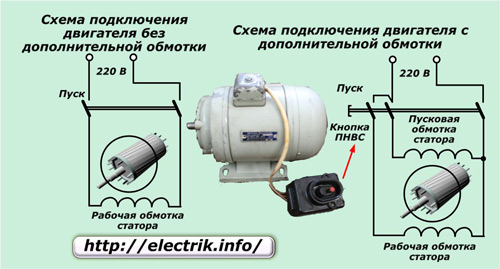
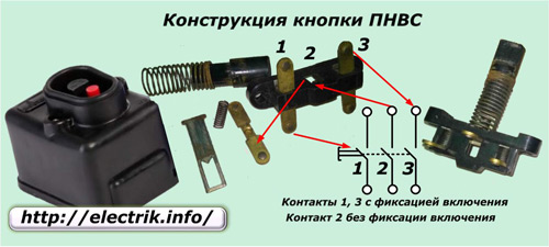
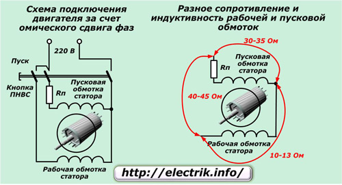
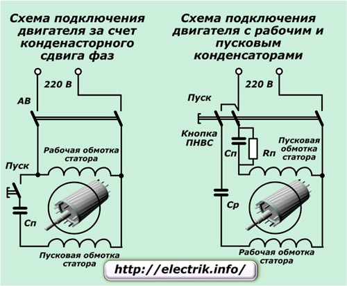
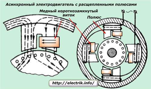
How rotor rotation is created in a single-phase asynchronous motor In the entire history of the operation of such devices, the following design solutions have been developed: 1. manual unwinding of the shaft with a hand or cord; 2. the use of an additional winding connected at the time of starting due to ohmic, capacitive or inductive resistance; 3. splitting by a short-circuited magnetic coil of the stator magnetic circuit. The first method was used in the initial development and did not begin to be applied in the future because of the possible risks of injuries at startup, although it does not require the connection of additional chains. Application of phase shifting winding in stator To give the initial rotation of the rotor to the stator winding, at the time of start-up, an additional auxiliary one is connected, but only 90 degrees shifted in angle. It is performed with a thicker wire to pass more currents than flowing in the working one. The connection diagram of such an engine is shown in the figure to the right. Here, a PNVS type button is used to turn on, which was specially created for such engines and was widely used in the operation of washing machines manufactured in the USSR. This button immediately turns on 3 contacts in such a way that the two extreme ones, after being pressed and released, remain fixed in the on state, and the middle one closes briefly, and then returns to its original position under the action of the spring. Closed extreme contacts can be disconnected by pressing the adjacent Stop button. In addition to the push-button switch, the following are used in automatic mode to disable the additional winding: 1. centrifugal switches; 2. differential or current relays; To improve engine starting under load, additional elements are used in the phase-shifting winding. Connection of a single-phase motor with starting resistance In such a circuit, ohmic resistance is sequentially mounted to the stator additional winding. In this case, the winding of the turns is carried out in a biffilar manner, providing a coefficient of self-induction of the coil very close to zero. Due to the implementation of these two techniques, when currents flow through different windings, a phase shift of about 30 degrees occurs between them, which is quite enough. The difference in angles is created by changing the complex resistances in each circuit. With this method, a starting winding with a low inductance and increased resistance can still be found. For this, winding with a small number of turns of a wire of lowered cross section is used. Connecting a single-phase motor with capacitor starting The capacitive phase current shift allows you to create a short-term connection of the winding with a series-connected capacitor. This chain only works when the engine enters the mode, and then turns off. The capacitor start creates the highest torque and a higher power factor than with a resistive or inductive start method. It can reach a value of 45 ÷ 50% of the nominal value. In separate circuits, a capacitance is also added to the working winding chain, which is constantly on. Due to this, deviations of currents in the windings by an angle of the order of π / 2 are achieved. At the same time, a shift of maximum amplitudes is noticeable in the stator, which provides good torque on the shaft. Due to this technique, the engine is capable of generating more power at start-up. However, this method is used only with heavy-start drives, for example, to spin the drum of a washing machine filled with linen with water. Capacitor trigger allows you to change the direction of rotation of the armature. To do this, just change the polarity of the connection of the starting or working winding. Split Pole Single Phase Motor Connection Asynchronous motors with a small power of about 100 W use splitting of the stator magnetic flux due to the inclusion of a short-circuited copper coil in the magnetic circuit pole. Cut into two parts, such a pole creates an additional magnetic field, which is shifted from the main one in angle and weakens it in the place covered by the coil. Due to this, an elliptical rotating field is created, forming a moment of rotation of a constant direction. In such designs, one can find magnetic shunts made of steel plates that close the edges of the tips of the stator poles. Engines of similar designs can be found in ventilating devices for air blowing. They do not have the ability to reverse.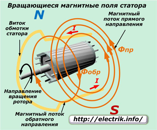
See also at i.electricianexp.com
:
