Categories: Sharing experience, Electric motors and their application
Number of views: 559167
Comments on the article: 27

How to determine the working and starting windings of a single-phase motor
 

How to determine the working and starting windings of a single-phase motor

Single-phase motors are electric machines of low power. In the magnetic circuit of single-phase motors there is a two-phase winding, consisting of the main and starting windings.

Two windings are needed in order to cause the rotation of the rotor of a single-phase motor. The most common motors of this type can be divided into two groups: single-phase motors with a starting winding and motors with a working capacitor.

For engines of the first type, the starting winding is switched on through the capacitor only at the time of starting and after the engine has developed a normal rotation speed, it is disconnected from the network. The engine continues to work with one working winding. The value of the capacitor is usually indicated on the nameplate of the motor and depends on its design.

For single-phase asynchronous AC motors with a working capacitor, the auxiliary winding is switched on continuously through the capacitor. The value of the capacitor’s working capacity is determined by the design of the engine.

That is, if the auxiliary winding of a single-phase motor is starting, its connection will only occur during start-up, and if the auxiliary winding is capacitor, then its connection will occur through a capacitor that remains on during the operation of the motor.

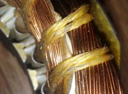
It is necessary to know the device of the starting and working windings of a single-phase motor. The starting and working windings of single-phase motors differ both in the cross-section of the wire and in the number of turns. The working winding of a single-phase motor always has a larger wire cross section, and therefore its resistance will be less.


Look at the photo clearly shows that the cross-section of the wires is different. A winding with a smaller cross section is the starting one. You can measure the resistance of the windings with both arrow and digital testers, as well as an ohmmeter. A winding in which the resistance is less is a working one.

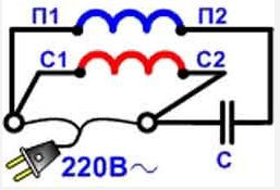
Working and starting windings of a single-phase motor

Fig. 1. The working and starting windings of a single-phase motor

And now a few examples you may come across:

If the motor has 4 outputs, then finding the ends of the windings and after measuring, you will now easily understand these four wires, the resistance is less - working, the resistance is more - starting. Everything is connected simply, 220v is supplied to thick wires. And one tip of the starting winding, on one of the workers. Which of them does not differ, the direction of rotation does not depend on this. The same is how you insert the plug into the outlet. The rotation will change, from connecting the starting winding, namely - changing the ends of the starting winding.

The following example. This is when the engine has 3 pins. Here the measurements will look as follows, for example - 10 ohms, 25 ohms, 15 ohms. After several measurements, find the tip from which the readings, with the other two, will be 15 ohms and 10 ohms. This will be one of the network wires. The tip, which shows 10 ohms, is also network and the third 15 ohms will be the trigger, which is connected to the second network through a capacitor. In this example, the direction of rotation, you will not change what it will be. Here, in order to change the rotation, it will be necessary to get to the winding circuit.

Another example where measurements can show 10 ohms, 10 ohms, 20 ohms. This is also one of the varieties of windings. Such, went on some models of washing machines, and not only. In these engines, the working and starting ones are the same windings (according to the design of three-phase windings). There is no difference what kind of worker you will have and what kind of starting winding. Connecting the starting winding of a single-phase motoralso carried through a capacitor.

See also at bgv.electricianexp.com:

  • Single-phase induction motor control device
  • How to choose capacitors for connecting a single-phase and three-phase electrode ...
  • Asynchronous micromotors
  • How to distinguish an induction motor from a DC motor
  • Connecting a three-phase motor to a household network

  •  
     
    Comments:

    # 1 wrote: Sergei | [quote]


    I have a single-phase motor with exactly the same windings, and you have written that "Starting and working windings differ in cross-section and number of turns", you should probably write that this is for many, but not all single-phase motors. And then people can get confused.

     
    Comments:

    # 2 wrote: Ruslan | [quote]


    Here is the detail!

    Thanks. I did not know this subtlety.

     
    Comments:

    # 3 wrote: Yuri | [quote]


    Thanks, I ran into production engines with a plug at 3 ends, the same resistance of the windings.

     
    Comments:

    # 4 wrote: | [quote]


    I have a single-phase asynchronous motor from a centrifugal fan for the filter above the stove. There were such in the 80s, snails with impellers on both sides of the engine. Two poles on opposite sides of the stator with the same winding thickness, 2 pairs of leads. The windings are interconnected on one side by a conductor in the cambric, so there is a connection between the windings. Let us denote the conclusions in pairs - 1 and 2, 3 and 4. Resistance between 1 and 2 63th, between 3 and 4 52th, between 1 and 3 4th, between 2 and 4 4th, between 2 and 3 57th. How this engine works and how to connect it, where the capacitor is, is unclear to me. I ask for clarification and advice.

     
    Comments:

    # 5 wrote: Maksim | [quote]


    Tell me how to check the capacitor on the capacitance from my tools, only the M266F Multimeter ?, the marking is erased

     
    Comments:

    # 6 wrote: Konstantin | [quote]


    It is very difficult to measure the capacitance of a capacitor with a multimeter. To do this, you need a special measuring bridge.

     
    Comments:

    # 7 wrote: | [quote]


    Not everything and not always so simple!
    There is a KD-50-U4 motor, single-phase, asynchronous. (here is the photo of the nameplate: alas, the link doesn’t work, whoever is interested in the photo or the link I will send), and so, according to the scheme proposed by the author, the resistance of the working winding is always less than the starting one, but in this case, the “red” winding is constantly turned on directly - 85.5 Ohms, and the “blue” winding connected through the starting capacitor is 65.5 ohms. However, in this case, it is not entirely correct to name the starting winding, rather it is phase shifting, in such engines, rotation is provided not by short-term start-up of the starting winding, but by a phase shift of the current. Both windings are constantly connected to the network. They are made with a wire of the same cross section and differ only in the number of turns, hence the different winding resistance.

     
    Comments:

    # 8 wrote: | [quote]


    Good evening.

    There is such a "tricky" and confusing question: is there a Chinese sharpener of 350 watts. Pavertek manufacturer. When the stone is loaded, it stops, the power is not enough. A friend suggested connecting the capacitor so that the auxiliary winding is constantly on and this will lead to the fact that the stone will not stop under load and more power will appear.

    QUESTION: Is that so for sure?
    And who was experimenting?
    What will such a connection lead to?
    Will it harm the motor or the capacitor?

    Thanks in advance for the full answer!

     
    Comments:

    # 9 wrote: | [quote]


    I have a single phase induction motor which has 3 pins. Can I connect 2 capacitors to a single-phase motor - the first for the starting winding and the second for the working ???

     
    Comments:

    # 10 wrote: | [quote]


    Engine ABE-071-4C, three wires. I make measurements red-green 22 OM; red-black 0.9 OM; green-black 22 OM. How to connect?

     
    Comments:

    # 11 wrote: | [quote]


    There is an emery 220v 450 in which capacitor is needed for operation. Output 4 wires. As I understand it, the ends that show little resistance to the plug And the other capacitor?

     
    Comments:

    # 12 wrote: | [quote]


    Hello. What is the magnitude of the resistance of the starting and operating windings from power or from what. I measured 0.6 ohms and a starting 2 ohms is this normal or not? With uv. Yuri.

     
    Comments:

    # 13 wrote: | [quote]


    Harold,
    Harold, YOU have a 2-speed engine, so you got so many values ​​when measuring, 63-57-52, 63 starting, 57 and 52 are working windings, something like that. I watched my hood, at me at all at 3 speeds. Good luck to you and positive in life!

     
    Comments:

    # 14 wrote: | [quote]


    I have a single-phase hoist, it is written for 600 kg. when it is necessary to raise kil 400 from the ground - no problem, but when the load hangs in the air - it can’t start, or even starts to unwind ... 2 kW engine, capacitors cost 20 microfarad + 40 microfarad starting .. I think the boost should be increased to 60 microfarad - what could be fraught?

     
    Comments:

    # 15 wrote: | [quote]


    Dear !!!! Help connect the electric motor from the meat grinder, there are two black, two yellow, red, and green !!! One black is connected to one capacitor, one yellow is connected to the second capacitor, a jumper between them !!!

     
    Comments:

    # 16 wrote: | [quote]


    Thanks a lot. This article really helped me)))

     
    Comments:

    # 17 wrote: | [quote]


    Thanks to the author. Easy, affordable and everything is clear)

     
    Comments:

    # 18 wrote: Ahmed | [quote]


    Good evening!
    Please explain how to connect a two-speed email. ABT71-115U2 engine from the BK-1500 air conditioner?
    Resistance between:
    I and II conclusions - 125 Ohms,
    I and III - 270 Ohms,
    I and IV - 182 Ohms,
    II and III - 144 Ohms,
    II and IV - 58 Ohms,
    III and IV - 202 Ohms.
    I would be grateful for the connection scheme. Thanks!

     
    Comments:

    # 19 wrote: hera | [quote]


    There is an electric motor from a baby with four wires with the same resistances of 19.2 ohms each pair of wires. How to connect?

     
    Comments:

    # 20 wrote: telemaster | [quote]


    Ahmed,
    based on (all) of your readings, the resistance between the 2 and 3 conclusions should be at least 390 OM you are correct measurements indicate the atom, I apologize horribly.

     
    Comments:

    # 21 wrote: Kostya | [quote]


    The author, I now have a motor, 180 watts, 4 wires coming out, I measured the resistance and on one winding 44 ohms, on the other 14 ohms, based on your "training record" it turns out that the winding on which 14 ohms goes to the network, and to which is 44 ohms per capacitor, according to your record, I have to connect one wire from the starting winding to one working wire and this will go to the network, and the other wire from less resistance will also go to the network and to the capacitor, and the wire from high resistance also to the capacitor and here is a problem, the wires on which there is more resistance ba shown in black, that is, they go into the network is operating winding and pad indicated by a different color and the resistance there is less in this engine no one altered, markerovka factory and need to connect all the opposite of your recording! Why is this so? Why fool others? According to your notes, you can burn the engine!

     
    Comments:

    # 22 wrote: Kostya | [quote]


    Harold,
    Have you already figured out how to connect or not?

    Alexander,
    Green-black network, red capacitor.

     
    Comments:

    # 23 wrote: Alexander | [quote]


    It is possible to change the direction of rotation of a single-phase capacitor motor with 3 outputs if you disassemble it and deploy the anchor, i.e., bring the motor shaft through the opposite cover, on the other hand.

     
    Comments:

    # 24 wrote: Ivan | [quote]


    Asynchronous single-phase wnk 315/1
    Knocks out the machine.
    4 pins:
    BLUE - ZERO
    BLACK - PHASE AND CAPACITOR
    BROWN - CONDENSER
    YELLOW GREEN - LAND.
    I measured the resistance with a multimeter:
    Kor-syn. 34 ohm
    Box Black 357 Ohm
    Blue - Black 323 Ohm
    Yellow-green at all ends shows about 20 megohms.
    What else can be checked and what is wrong with measurements. I ask for help. Thanks.

     
    Comments:

    # 25 wrote: Vova | [quote]


    Dear, do not tell me, you may know the DKV-3 engine. its parameters and circuit diagram. I did not find it on the internet. The output is 3 wires. winding resistance 65 ... 60 .... 7.ohm. collector. There are 2 windings in the stator .. the rotor is multi-band. According to your explanation, I will probably figure it out. By selecting the voltage ... but I would like for sure ..

     
    Comments:

    # 26 wrote: Anton | [quote]


    Ivan,
    Swap blue and brown
     
    Comments:

    # 27 wrote: Edward | [quote]


    I have an old Soviet engine with three windings, two of which give 58 Ohms, and the third 59 Ohms. How to connect it?