Categories: Featured Articles » Novice electricians
Number of views: 162,299
Comments on the article: 4
What is zero and phase?
Such a question sometimes arises for novice electricians or apartment owners who are well versed in a set of repair tools, but previously did not particularly delve into the wiring device. And then the moment came when the outlet has stopped working or a light in the chandelier shines, but I don’t want to call an electrician and there is a great desire to do everything myself.
In this case, the primary task of the home master is not to eliminate the malfunction, as it seems at first glance, but to comply with electrical safety rules, eliminating the possibility of falling under the influence of electric current. For some reason, many forget about it, neglecting their health.
All current-carrying parts of the wiring must be reliably insulated, and the contacts of the sockets are hidden deep into the case so that there is no possibility of accidental contact with exposed parts of the body. Even the mechanical design of the plug inserted into the socket is thought out in such a way that it is quite problematic to hold onto both contacts and get under the influence of electric current.
In everyday life, we do not notice this, and consciousness has already developed the habit of not paying attention to electricity, which can be detrimental during repair work with electrical appliances. Therefore, study the basic safety rules and be careful when handling electricity.
How is household wiring
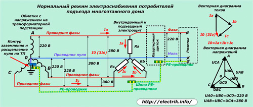
Electricity to a residential building comes from a transformer substation, which converts the high voltage voltage of an industrial power supply network to 380 volts. The secondary windings of the transformer are connected according to the “star” scheme when the three terminals are connected to one common point “0”, and the remaining three are connected to terminals “A”, “B”, “C” (for enlargement, click on the figure).
The ends “0” connected together are connected to the ground circuit of the substation. Here, the splitting of zero by;
-
working zero shown in the picture in blue;
-
protective PE conductor (yellow-green line).
Under this scheme, all newly built houses are created. It is called TN-S system. She has three phase wires and both of the listed zeros at the entrance to the inside of the switchboard at home.
In buildings of the old construction, there are still often cases of the absence of a PE conductor and a four-, rather than a five-wire circuit, which is indicated by the index TN-C.
Phases and zeros from the output winding of the TP through air wires or underground cables are fed to the input shield of a multi-storey building, forming a three-phase voltage system 380/220 volts. She gets divorced on the drive shields. Inside the apartment there is a voltage of one phase 220 volts (wires “A” and “O” are highlighted in the picture) and protective conductor PE.
The last element may be absent if the reconstruction of the old wiring of the building is not carried out.
Thus, "Zero" in the apartment they call a conductor connected to the ground circuit in a transformer substation and used to create a load from "Phases"connected to the opposite potential end of the winding on the TP. Protective zero, also called a PE-conductor, is excluded from the power supply circuit and is intended to eliminate the consequences of possible malfunctions and emergency situations in order to divert the arising fault currents.
The loads in this scheme are distributed evenly due to the fact that on each floor and risers, wiring and connection of certain apartment shields to specific 220 volt lines inside the access switchboard are made.
The system of voltage supplied to the house and the porch is a uniform "star", repeating all the vector characteristics of the TP.
When all electrical appliances are turned off in the apartment, and there are no consumers in the sockets and the voltage is connected to the panel, then the current in this circuit will not flow.
The sum of the currents of the three-phase network is summed up according to the laws of vector graphics in the neutral wire, returning to the windings of the transformer substation with the value I0, or as it is also called 3I0.
This is a working, optimal and proven over many years power supply system. But, in it, too, as in any technical device, breakdowns and malfunctions can occur. Most often they are associated with poor quality contact connections or a complete breakdown of conductors in various places of the circuit.
What is accompanied by a wire break in zero or phase
It is not difficult to tear off or simply forget to connect the conductor to some device inside the apartment. Such cases occur as often as the burning of metal conductors with poor electrical contact and increased loads.
If the connection of any power receiver to the apartment shield is lost inside the apartment wiring, this device will not work. And it’s absolutely not important what is broken: a chain of zero or phase.
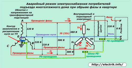
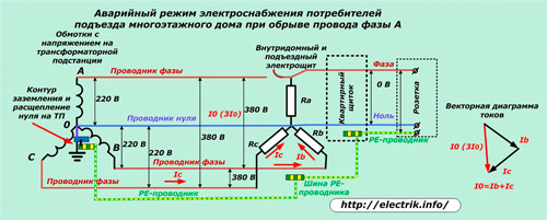
The same picture manifests itself in the case when there is a break in the conductor of any phase supplying the inside or access electrical switchboard. All apartments connected to this line with a malfunction that has ceased to receive electricity.
Moreover, in two other chains, all electrical appliances will function normally, and the current of the working neutral conductor I0 is summed from the two remaining components and will correspond to their value.
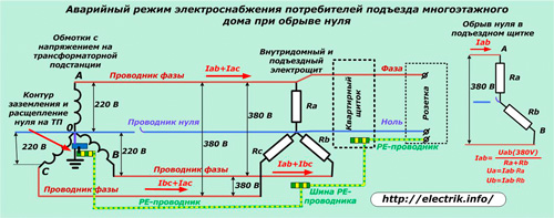
As you can see, all of the listed wire breaks are associated with a power outage from the apartment. They do not cause damage to household appliances. The most dangerous situation arises when the connection between the ground circuit of the transformer substation and the midpoint of the load connection of the house or entrance electrical switchboard disappears.
This situation can arise for various reasons, but most often it manifests itself during the work of teams of electricians who own the adjacent specialty of tasters ...
In this case, the path of the passage of currents along the working zero to the ground loop (A0, B0, C0) disappears. They begin to move along the external circuits of AB, AC, CA to which a total voltage of 380 volts is connected.
On the right side of the picture it is shown that the current IAB appeared when the line voltage was connected to the series-connected loads Ra and Rv of two apartments. In this situation, one owner can economically turn off all electrical appliances, and the other - use them to the maximum.
As a result of the Ohm's law U = I ∙ R, a very small voltage value can appear on one apartment panel, and close to a linear value of 380 volts on the second. It will cause damage to the insulation, the operation of electrical equipment at off-design currents, increased heating and breakdowns.
To prevent such cases, there are protection against overvoltage, which are mounted inside the apartment panel or expensive electrical appliances: refrigerators, freezers and similar devices of world famous manufacturers.
How to determine zero and phase in home wiring
In the event of a malfunction in the electrical network, home masters most often use a cheap Chinese-made voltage indicator screwdriver, shown on the top of the picture.
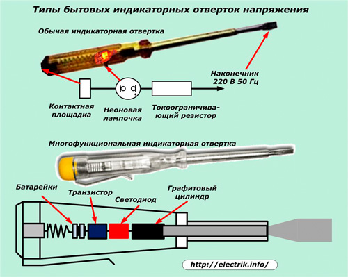
It works on the principle of passing capacitive current through the body of the operator. For this, inside the dielectric housing are placed:
-
a bare tip in the form of a screwdriver for connection to the phase potential;
-
a current limiting resistor that reduces the amplitude of the passing current to a safe value;
-
a neon bulb, the glow of which during the flow of current indicates the presence of a phase potential in the test area;
-
a contact area for creating a current circuit through the human body to the potential of the earth.
Qualified electricians use more expensive multifunctional indicators in the form of screwdrivers with an LED to check the presence of a phase, the glow of which is controlled by a transistor circuit powered by two built-in batteries that create a voltage of 3 volts.
Such indicators, in addition to determining the phase potential, are capable of performing other additional tasks. They do not have a contact area, which must be touched when measuring. More information on how various screwdriver indicators are arranged and work is described here: Voltage indicators and indicators.
A method for checking the presence and absence of voltage in the sockets of an ordinary outlet with a simple indicator is shown in the photographs below.
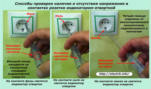
The left picture clearly shows that the glow of the indicator lamp in daylight is poorly noticeable, therefore, requires increased attention when working.
The contact on which the indicator lights up is a phase. At the working and protective zero, the neon bulb should not glow. Any reverse action of the indicator indicates a malfunction in the wiring diagram.
When operating such a screwdriver, it is necessary to pay attention to the integrity of the insulation and not to touch the exposed terminal of the indicator, which is under voltage.
The following photos show a method for determining the voltage in the same outlet using an old tester operating in a voltmeter mode.
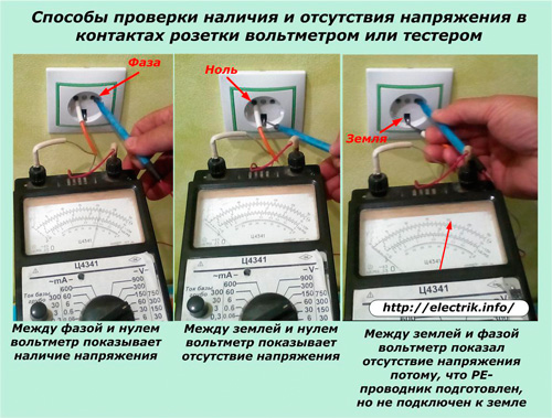
The arrow indicates:
-
220 volts between phase and operating zero;
-
lack of potential difference between working and protective zero;
-
lack of voltage between phase and protective zero.
The latter case is an exception. The arrow in the normal circuit should also show a voltage of 220 volts. But it is not in our outlet for the reason that the building of the old building has not yet passed the stage of reconstruction of electrical wiring, and the landlord, who completed the last repair, made the PE conductor wiring in his premises, but did not connect it to the grounding contacts of the sockets and the PE- bus conductor housing shield.
This operation will be carried out after the transfer of the building from the TN-C system to the TN-C-S. When it is completed, the voltmeter needle will be in the position indicated by the red line, indicating 220 volts.
Several ways to determine the phase and neutral wires: How to find phase and zero
Troubleshooting Features
A simple determination of the presence or absence of voltage does not always accurately determine the state of the circuit. The presence of different positions of the switches can lead the master astray. For example, the picture below shows a typical case when there is no voltage at the point “K” when the switch is off on the phase wire of the lamp, even with a working circuit.
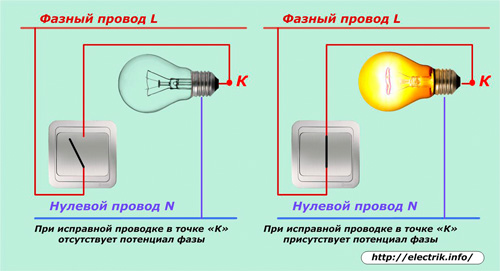
Therefore, when conducting measurements and troubleshooting, all possible cases should be carefully analyzed.
An example of a step-by-step troubleshooting in an idle chandelier using an indicator screwdriver is shown here:What to do if the chandelier does not work
See also at i.electricianexp.com
:

