Categories: Featured Articles » Electrician Secrets
Number of views: 40293
Comments on the article: 4
Typical schemes for connecting a three-phase motor to a single-phase network
Of all the methods for connecting an induction motor developed by numerous researchers, in practice two are most often used, called methods:
1. stars;
2. The triangle.
Both of them use a capacitor trigger, characterized by an accessible elemental base.
The name of each method is given by the method of connecting the stator windings to the network. Their diagram has already been shown here: Single-phase connection of a three-phase motor. You can find out how they are assembled in a particular engine using a plate mounted on the body.
Usually, even on older models, you can make out the method of connecting the windings and the mains voltage for which they are created. Such information can be trusted if the engine has already been tested in operation and there are no complaints about it. But, even in this case, it is necessary to conduct electrical measurements.
How to check the wiring diagram of the motor windings
Let's start with a poor version of the installation of stator windings, when their ends are not marked at the factory, and the zero assembly for the star circuit is made inside the housing and brought out by one common core. We'll have to disassemble the case, remove the covers, dismantle the internal connection, separate the wires.
Determination of stator phases
After that. an ohmmeter is used as the ends of the wires are disconnected. One of its probes is connected to an arbitrary wire, while others find its end according to the ohmmeter. Also act with the rest of the phases. Do not forget to label or label them in some accessible way.
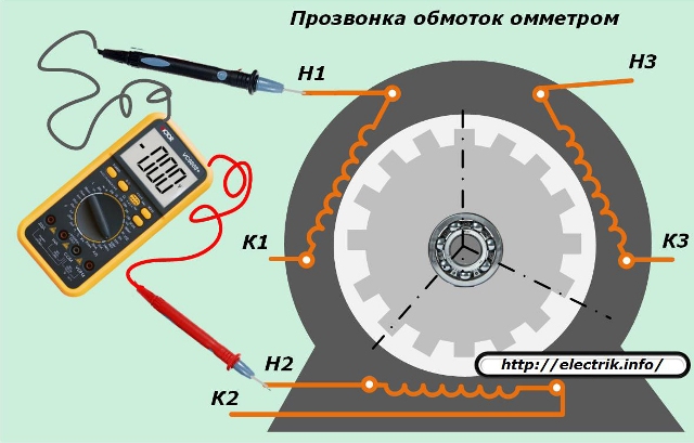
Instead of an ohmmeter, you can use home-made tones, consisting of a battery with a light bulb and wires.
Determination of the polarity of the windings
To find the same spaced ends, it is recommended to use one of two methods:
1. by applying a direct current pulse;
2. by connecting an AC voltage source.
Both of these options work by supplying electrical voltage to one winding and transforming it into the rest through the core core.
Test Method with Battery and DC Voltmeter
The principle of operation is shown in the picture.
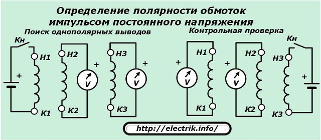
A sensitive DC voltmeter, capable of responding to the appearance of a pulse, should be connected to the terminals of one of the windings. A voltage is applied to another winding for a short time by a certain pole, for example, a plus.
At the moment of applying the pulse, a voltmeter reading is observed: the arrow may deviate to the positive or negative side. Its movement to the plus means the coincidence of the polarities of both windings (opening the contact - arrow to the minus). The procedure is repeated for the third winding.
By changing the windings for connecting the batteries, a control check of the marking is carried out.
AC Voltage Test Method
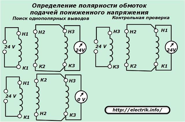
Two arbitrary windings are connected in parallel with connected ends to a voltmeter, and the third is supplied with voltage from a transformer. The voltmeter readings are controlled: if the polarities of both windings coincide, the voltage of the EMF source will be displayed on the voltmeter, and in case of violation, it will be zero.
By changing the position of the transformer to another winding and switching the voltmeter circuits, the polarity of the third phase is checked, and then control measurement is performed.
About how to identify faults in the winding, see here: How to check the status of an induction motor winding
Star launch pattern
It is provided by a winding connection scheme using three different circuits - phases combined by a common point, neutral.
The circuit is assembled after checking the polarity of the connection of the stator windings inside the motor.A two-phase voltage of 220 volts by phase through a circuit breaker is applied to the beginning of two different windings. To one of them capacitors cut into the gap: starting and working.
Zero power supply is supplied to the third output of the star.
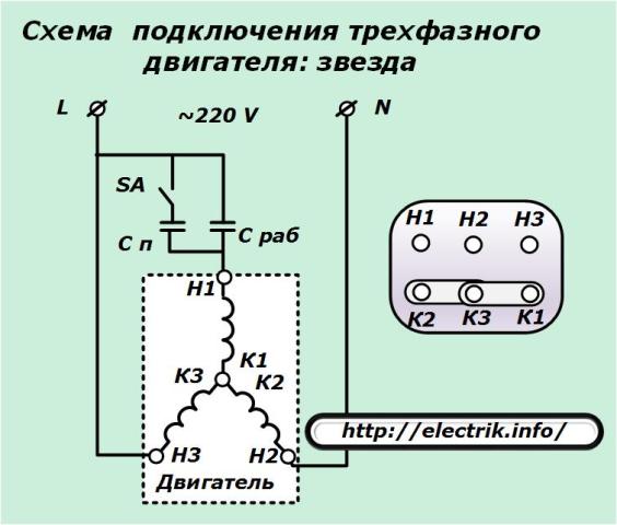
The capacity of the working capacitors is selected according to the empirical formula:
C slave = (2800·I) / U.
For the starting circuit, this value is increased by 2–3 times. During the operation of the motor under load, it is necessary to check the current ratios in the windings by measuring and adjust the working capacitors in relation to the average drive loads. Otherwise, equipment will overheat, leading to aging of the insulation.
It is convenient to connect the electric motor to the work through the design of a special switch that was previously made for washing machines with a Riga centrifuge.
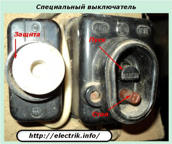
A pair of make contacts is already integrated here, which simultaneously supply voltage to two parallel-connected circuits by pressing the Start button. And when you release this button, one chain is broken. This contact is also used for the starting chain.
General disconnection of voltage is done by pressing the Stop button.
Triangle trigger pattern
It repeats the algorithm of the previous scheme in terms of startup, but differs in the way the stator windings are connected.
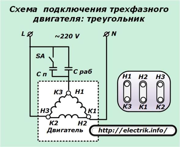
The currents flowing in them exceed the values for the chains of the star. Working capacitors require large ratings. They are calculated by the following expression:
C slave = (4800·I) / U.
The correctness of the selection of capacitors is also determined by the ratio of currents in the stator windings with control measurements under load.
See also at bgv.electricianexp.com
:
