Categories: Novice electricians, Electric motors and their application
Number of views: 148,048
Comments on the article: 8
How to check the electric motor - simple tips for electricians
In our daily lives, we constantly encounter various electrical devices that greatly facilitate our activities. Almost all of them have in their design an engine powered by electricity to perform a certain job.
Sometimes, for various reasons, malfunctions arise in it. It is necessary to determine its performance, to identify and repair damage.
How is the electric motor
Immediately make a reservation that we will not resort to complex technical descriptions and formulas, but try to use simplified schemes and terminology. We also take into account that working with electric motors in electrical installations is dangerous. They are allowed trained, trained personnel.
Attention: Self-repair of the electric motor by unskilled workers can end tragically!
Kinematic diagram
By mechanical design, any electric motor can be represented as consisting of only two parts:
1. permanently fixed, which is called a stator and is attached to the body of the machine, mechanism or held in hands, as on a drill, punch and similar devices;
2. mobile - a rotor performing a rotational motion transmitted to an actuator.
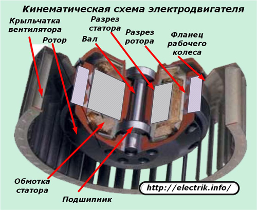
Both of these halves are completely separated from each other, but are in contact through bearings. Nowhere and in no place do they contact mechanically purely mechanically. The rotor is inserted inside the stator and rotates completely freely in it.
This ability to rotate must be evaluated first of all when analyzing the operability of any electric machine.
To check rotation, you must:
1. completely remove the voltage from the power circuit;
2. Try to manually rotate the rotor.
The first action is a necessary requirement of safety rules, and the second is a technical test.
It is often difficult to evaluate rotation due to the connected drive. For example, the rotor of the engine of a working vacuum cleaner is quite easy to unwind with a movement of the hand. To rotate the shaft of the working punch, you will have to apply force. To roll the shaft of an engine connected through a worm gearbox will not work at all due to the design features of this mechanism.
For these reasons, the rotor rotation in the stator is evaluated when the drive is disconnected and the quality of the bearings is analyzed. It can hinder movement:
-
wear of slip pads;
-
lack of lubrication in bearings or its improper use. For example, the usual solid oil, which is often filled with ball bearings, will thicken in the cold and can cause poor engine starting;
-
dirt or foreign objects between the moving and stationary parts.
Noise during engine operation is created by faulty, broken bearings with increased play. For its quick assessment, it is enough to sway the rotor relative to the stationary part, creating variable loads in the vertical plane, and try to push and pull it along the axis. On many models, minor play is considered acceptable.
If the rotor rotates freely and the bearings work well, then it is necessary to look for a malfunction in the electromagnetic circuits.
Electric circuit
For any engine to work, two conditions must be met:
1. on its winding (or windings in multiphase models) to bring the rated voltage;
2. The electrical and magnetic circuits must be operational.
Where to check the voltage of the motor
Consider the first position on the example of the design of an electric drill with commutator motor.
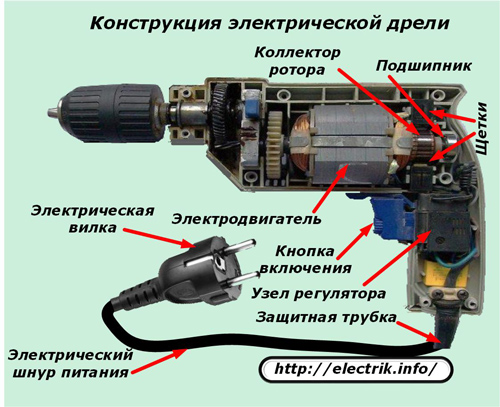
If you insert a plug into a power outlet with a working voltage at a working drill, then this is not enough to start the engine. You will need to press the power button again.
Only then the electric current from the plug through the cord through the triac control unit and the contacts of the pressed button will come to the brush unit located on the collector, and through it can get to the winding.
To summarize: to make a conclusion about the health of the drill motor is possible only after checking the voltage on the brushes of the collector assembly, and not on the contacts of the plug. The above example is a special case, but reveals the general principles of troubleshooting, typical for most electrical devices. Unfortunately, some electricians in a hurry neglect this position.
Types of electrical circuits of electric motors
Electric motors are designed to operate on direct or alternating current. Moreover, the latter are divided into:
-
synchronous when speed rotor speed andthe electromagnetic field of the stator match;
-
asynchronous - with a lagging frequency.
They have different design features, but general principles of operation, based on the action of the rotating electromagnetic field of the stator on the rotor field, transmitting rotation to the drive.
DC motors
They are made for use as coolers for computer devices, starters for cars, powerful diesel stations, combine harvesters, tanks and other tasks. The device of one of these simple models is shown in the picture.
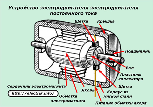
The stator's magnetic field in this design is created not by permanent magnets, but by two electromagnets assembled on special cores - magnetic cores, around which coils with windings are located.
The magnetic field of the rotor is created by the current passing through the brushes of the collector assembly along the winding laid in the slots of the armature.
AC induction motors
The section of one of the models shown in the picture shows a certain similarity with the previously considered device. Design differences are in the implementation of the rotor in the form of a short-circuited winding (without direct supply of current from the electrical installation to it), called the "squirrel wheel" and the principles of arrangement of turns on the stator.
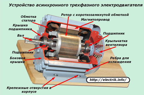
Synchronous AC Motors
Their windings of the stator coils are located at the same angle of displacement between themselves. Due to this, an electromagnetic field rotating at a certain speed is created.
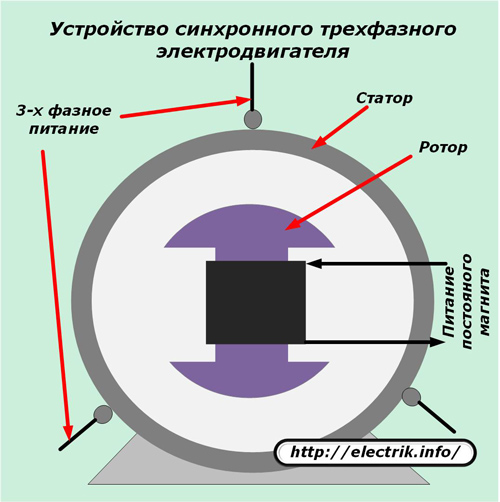
A rotor electromagnet is placed inside this field, which, under the influence of applied magnetic forces, also begins to move with a frequency synchronous to the rotation speed of the applied force.
Thus, in all considered engine schemes, the following are used:
1. windings of wires to enhance the magnetic fields of individual turns;
2. magnetic cores for creating paths of magnetic flux;
3. electromagnets or permanent magnets.
For individual designs of engines, called collector engines, a current transfer scheme from the stationary part to rotating parts through the brush holder assembly is used.
In all of these technical devices, various malfunctions can occur that affect the operation of a particular engine.
Since the magnetic circuit is created at the factory from plates of special steels assembled with high reliability, breakdowns of these elements occur very rarely, and even then under the influence of an aggressive environment that is not provided for by the operating conditions or due to unforeseen transcendent mechanical loads on the case.
Therefore, verification of the passage of magnetic fluxes is practically not carried out, and all attention in the event of malfunctions of electric motors after evaluating the mechanics is drawn to the state of the electrical characteristics of the windings.
How to check the brush assembly of the commutator motor
Each collector plate is a contact connection of a certain part of the continuous winding of the armature and an electric current passes through its connection to the brush.
A working engine in this unit creates a minimum transient electrical resistancethat does not have a practical effect on the quality of work and power output. The appearance of the plates is clean, and the gaps between them are not filled with anything.
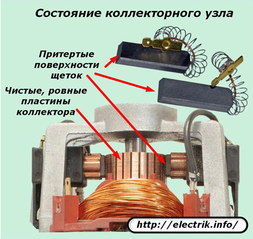
Engines that have been subjected to severe stress have dirty manifold plates with traces of graphite dust that has accumulated in the grooves and impairs insulation properties.
The engine brushes are pressed against the plates by spring force. Graphite gradually erases during operation. Its rod wears out in length, and the force of pressing the spring decreases. When the contact pressure is weakened, the transient electrical resistance increases, which causes sparking in the collector.
As a result, increased wear of the brushes and copper plates of the collector begins, which can cause engine damage.
Therefore, it is necessary to check the brush mechanism, inspect the cleanliness of the surfaces, the quality of the production of brushes, the working conditions of the springs, the absence of sparking and the appearance of a round fire during operation.
Contamination is removed with a soft cloth moistened with a solution of industrial alcohol. The gaps between the plates are cleaned with ravens from solid non-resinous wood species. The brushes are rubbed with a fine-grained emery cloth.
If potholes or burnt areas appear on the collector plates, the collector is machined and polished to a level at which all irregularities are eliminated.
A well-fitted brush assembly must not create sparks during operation.
How to check the insulation status of the windings relative to the housing
To detect a violation of the dielectric properties of the insulation relative to the stator and rotor, it is necessary to use a device specially designed for these purposes - megaohmmeter.
It is selected by the magnitude of the output power and voltage.
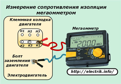
Initially, the measuring ends are connected to the common terminal of the terminals of the windings and the ground bolt of the housing. In an assembled motor, the electrical contact of the stator and rotor housings is created through metal bearings.
If the measurement shows normal insulation, then this is quite enough. Otherwise, all windings are disconnected and a search for insulation violation is carried out by measuring and inspecting individual circuits.
The reasons for the poor condition of the insulation can be different: from mechanical damage to the paint coating layer of the wires to high humidity inside the case. Therefore, they must be precisely determined. In some cases, it is good enough to dry the windings, and in others it is necessary to look for places with scratches or scuffs to exclude leakage currents.
Continuation of the article:How to check the status of the winding of an electric motor
See also at i.electricianexp.com
:
