Categories: Novice electricians, Industrial electrician
Number of views: 127159
Comments on the article: 8
How to use a megaohmmeter
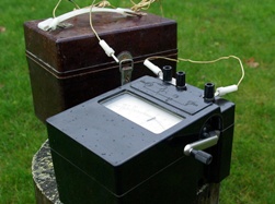 The name of this device is composed of three words: “mega”, which indicates the dimension of the measurement value (thousand thousand or 106), "Ohm" is the unit of electrical resistance, "meter" is the abbreviation of measuring. Immediately it becomes clear the technical purpose of the device: the measurement of electrical resistance in the range of megaohms.
Often, connoisseurs of the Russian language correct this word, excluding the letter “a” from it under the pretext that two vowels in a row during pronunciation are dissonant. But this technique distorts the meaning embedded in the device in the same way as the slang of individual electricians - “meger”.
The principle of measuring insulation resistance with a megohmmeter
The device is based on the famous Ohm's law for a section of the circuit I = U / R. For its implementation inside the case, any modification has built-in:
-
source of constant, calibrated voltage;
-
current meter;
-
output terminals.
The design of the voltage generator can vary significantly and can be created on the basis of simple manual dynamo cars, as in older models, or through the use of power from a built-in or external source.
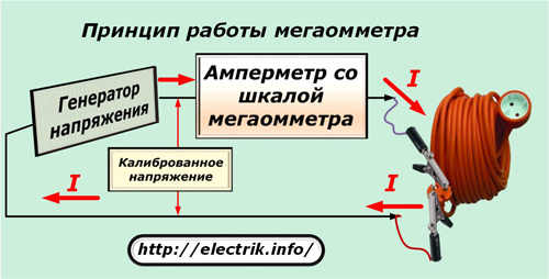
The output power of the generator, as well as the magnitude of its voltage, can include several ranges or be performed by a single, fixed value.
Connecting wires are connected to the terminals of the device, the other end of which is connected to the measured circuit. Crocodile clips are commonly used for these purposes.
Ammeter built into the electrical circuit measures current passing through the circuit. Given that the voltage of the generator is already known and calibrated, the scale of the measuring head is calibrated immediately in the converted resistance units - megaohms or kilo-ohms.
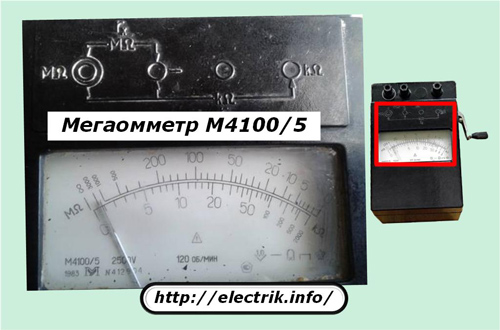
This is how the scale of the old analogue instrument of the M4100 / 5 series, tested over fifty years of operation, looks like. It allows you to take measurements on two scales:
1. megaohms;
2. kilo-ohms.
If the megaohmmeter is created using new technologies for processing digital signals, then its display also shows resistance, but in a more visual form.
How a megohmmeter works
Consider this issue on the example of a simplified electrical circuit of an analog device.
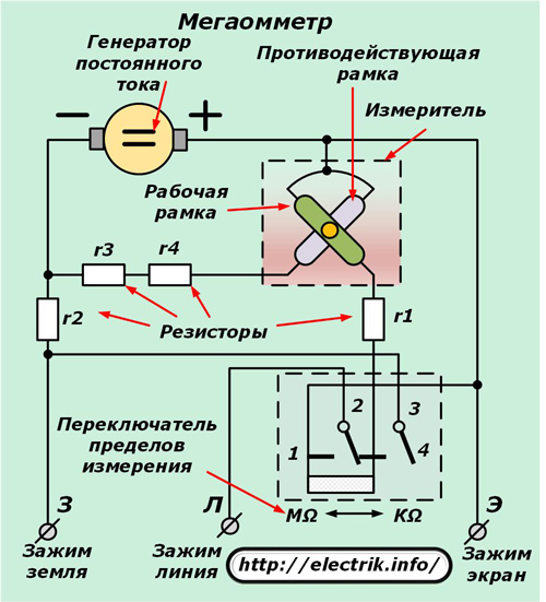
During its analysis, the components are clearly distinguished:
-
DC generator;
-
measuring head assembled on the basis of the principle of interaction of two frames (working and counteracting);
-
toggle-switch for measuring limits, which allows switching various resistor chains to change the output voltage and operating mode of the head;
-
current limiting resistors.
A fairly simple scheme does not contain any extra elements. On a sealed, durable dielectric casing of such a device are placed:
-
handle for easy transportation;
-
folding portable generator handle, which must be rotated to generate voltage;
-
toggle lever for switching measurement modes;
-
output terminals for connecting the connecting wires of the circuit.
Almost all megaohmmeter designs have three output terminals, which are called:
-
З - earth;
-
L is the line;
-
E - screen.
The earth and line terminals are used in all measurements of insulation resistance relative to the ground loop, and the screen output is designed to eliminate the influence of leakage currents when measuring between two parallel conductors of a cable or other similar live parts.
For its inclusion in the work, it is necessary to use one measuring wire of a special design with shielded ends. It always comes with a device at the factory. It has two terminals at one end, one of them is marked with the letter E.This pin is connected to the corresponding terminal of the megohmmeter.
An example of connecting the measuring ends to the device is shown in the figure.
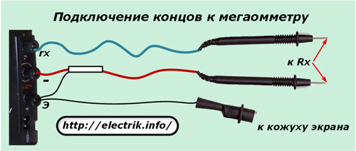
Here, instead of terminals “L” and “Z”, the indices “rx” and “-” are used. This is just a new marking that replaces the old one on modern appliances.
The picture shows that the terminal “E” is used to connect to the screen or casing. Use it for special accurate measurements. Megaohmmeters using power to the generator from internal batteries or an external network. work on the same principles. Only they do not need to twist the knob. To issue voltage to the circuit under test, they hold the button pressed. Moreover, for devices capable of producing several combinations of voltages, not one, but two, three buttons or their combinations are used.
The internal structure of such megaohmmeters is much more complicated. We do not consider it here, since this issue relates more to repair work, and not to measurements.
The voltage generated by the megaohmmeter generator of various models can be one of the following values: 100, 250, 500, 700, 1000, 2500 volts. Moreover, some devices operate on the same range, while others have several.
The output power of devices designed to test the insulation of industrial high-voltage equipment can be several times higher than the characteristics of models designed for use in household electrical wiring. The dimensions of such devices will also vary.
For this reason, focusing on small designs that can be kept in a jacket pocket may not be justified in all cases.
What to look for when working with a megaometer
Instrument overvoltage
The output power of the megaohmmeter generator is quite enough to not only determine the appearance of microcracks in the insulation layer, but also to cause serious electrical injury.
For this reason, safety rules permit the use of the device only by trained and well-trained personnel authorized to work in live electrical installations. And this is at least the third TB group.
The increased voltage of the device during measurement is present on the tested circuit, connecting wires and terminals. To protect against it, special probes are used mounted on test leads with a reinforced insulation surface.
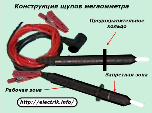
At the ends of the probes with safety rings, a restricted area is highlighted. It should not be touched by exposed parts of the body. Otherwise, you can be affected by voltage.
For manipulations with measuring probes, hands are taken on the surface of the working area. During measurements, well-insulated crocodile clips are used to connect to the circuit. The use of other wires and probes is prohibited.
During the measurement, there should be no people in the entire test area. This is especially true when measuring the insulation resistance of long cables, the length of which can be several kilometers.
Induced voltage
The energy passing through the wires of the power lines has a large magnetic field, which, changing according to the sinusoidal law, induces a secondary EMF and current I2 in all metal conductors. Its value on extended products can reach large values.
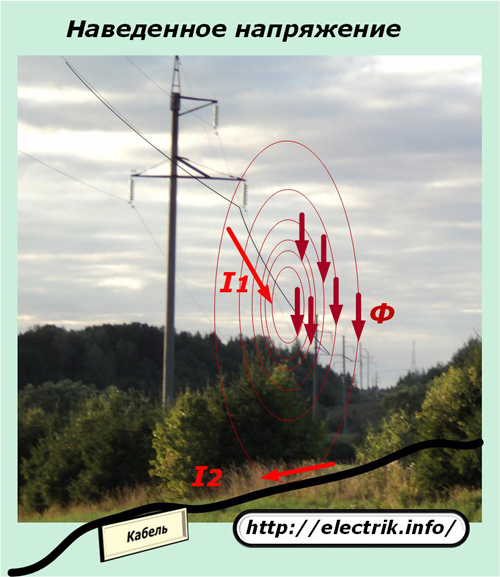
This factor must be considered for two reasons related to:
1. the accuracy of the measurement;
2. the safety of working personnel.
The first reason is that when assembling the circuit to measure the insulation resistance, a current of unknown magnitude and direction will flow through the megaohmmeter measuring unit, caused by the induction of electrical energy. Its value will be added to the instrument reading from the calibrated voltage of the generator.
As a result, two unknown current values are summed up arbitrarily and create an unsolvable metrological problem.The measurement of the resistances of electrical circuits under any voltage, and not just under induced, is therefore completely meaningless.
The second reason is due to the fact that work under induced voltage can lead to electrical injuries and require strict observance of safety rules.
Residual charge
When the generator of the device supplies voltage to the measured network, a potential difference is created between the electrical bus or the wire of the line and the earth circuit and a capacitance is formed that receives a charge.
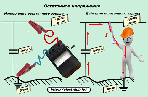
After the megohmmeter circuit breaks due to disconnection of the measuring wire, a part of this potential is preserved: the bus or wire has a capacitive charge. As soon as a person touches this area, he receives an electrical injury from the discharge current through his body.
For this reason, it is necessary to take additional safety measures and constantly use portable grounding with an insulated handle to safely remove capacitive voltage.
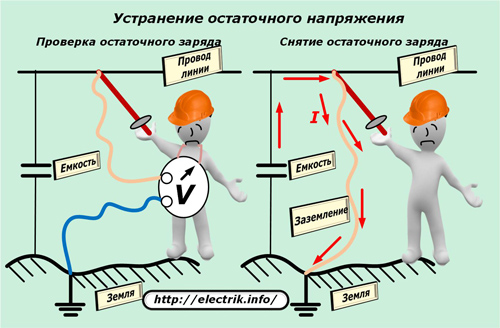
Before connecting a megohmmeter to the circuit, the insulation of which will be measured, it is always necessary to verify the absence of voltage or residual charge on it. This is done with a tested indicator or a verified voltmeter of the corresponding ratings.
After each measurement, the capacitive charge is removed by portable grounding using an insulating rod and other additional protective equipment.
Usually a megaohmmeter needs to be taken many measurements. For example, to draw a conclusion about the quality of insulation of a control ten-core cable, it is required to check it relative to the ground and each core and between all wires alternately. At each measurement, use portable grounding.
For quick and safe operation, one end of the grounding conductor is initially connected to the ground loop and left in this position until the work is completed.
The second end of the wire is attached to an insulating rod and with it, grounding is applied each time to remove the residual charge.
Basic rules for the safe use of a megohmmeter
Verification and testing
Any work in electrical installations is allowed to be performed only by working electrical devices.
With reference to a megaohmmeter, this means that it must meet two requirements simultaneously and be:
1. tested;
2. Attorney.
Testing means checking the resistance of its own insulation and all components in an electrical testing laboratory with overvoltage. On the basis of it, the owner of the device is issued a certificate authorizing the operation of the megohmmeter for a specific, limited period.
Verification is carried out by specialists of the metrology laboratory in order to determine the accuracy class of the device and apply a stamp on its body to pass control measurements. The owner is obliged to take measures to preserve the applied stamp with the date and number of the witness. If it disappears, then the device is automatically considered faulty.
Types of jobs
A megohmmeter is selected for each measurement primarily in terms of the output voltage. They can perform two different types of checks:
1. insulation tests;
2. measurement of the resistance of the dielectric layer.
The first method involves creating an extreme case for the test site. For this purpose, it is not supplied with a rated voltage, but an overstated voltage, provided for by the technical documentation. The test time is also chosen quite large. This allows you to timely identify all insulation defects and exclude their manifestation during operation.
The second method uses a more sparing mode. The voltage for it is selected at a lower value, and the measurement time is determined by the duration of the end of the capacitive charge of the measuring section.For electrodynamic devices, it does not exceed a minute (it is necessary to turn the knob so much at a speed of 120 ÷ 140 rpm), and for electronic devices it takes about 30 seconds (keep the button pressed).
For example, the measurement of the insulation resistance of a particular electrical circuit must be performed with a megohmmeter that produces 500 volts at the output. Then to test it, you need a 1000 V device.
Insulation measurement is carried out by electrical personnel of various professions, and the test function is provided only to specialists in the insulation service laboratory. Quite often, they do not have the capabilities of a megohmmeter for these purposes, and they include additional installations and sources of extraneous voltage, which have higher capacities and measuring capabilities.
Knowledge of the features of the tested circuit
Before applying high voltage to the measured area, it is necessary to take measures to prevent breakdowns and malfunctions of its components. In modern electrical equipment there are many semiconductor elements, various capacitors, measuring and microprocessor devices. They are not designed for the operating conditions that the megohmmeter generator voltage creates.
All such devices must be protected. To do this, they are removed from the circuit or shunted in a certain way.
After the end of measurements, the entire circuit should be restored and brought into working condition.
How to measure insulation resistance
The technological process is recommended to be divided into three main stages:
1. preparatory part;
2. taking measurements;
3. The final stage.
During preparation necessary:
-
decide organizational activities, determine the performers and their qualifications;
-
familiarize yourself with the wiring diagram and provide measures to prevent breakdowns of its components;
-
prepare protective equipment and serviceable measuring instruments;
-
to take a section of electrical equipment out of work.
Before starting work with a megaohmmeter it is important to verify its serviceability. To do this, connect test leads to its terminals and short their output ends together. Then voltage is supplied from the generator and the reading is monitored.
A serviceable device should measure the shorted circuit and show a result of 0. Then the ends are disconnected, taken to the sides and re-measured. The scale should already display another value - ∞. This is the insulation resistance of the air gap between the open ends of the megohmmeter.
Based on these two indications, a conclusion is drawn about the technical health of the device, the integrity of the connecting wires and the readiness for work.
Take a direct measurement insulation resistance of one wire is reduced to a strict sequence of actions:
1. connecting a portable ground to the ground loop;
2. checking and ensuring the absence of voltage on the test site;
3. installation of portable grounding for the period of connecting the device;
4. assembly of the megohmmeter measurement circuit;
5. removal of portable grounding;
6. applying a calibrated voltage to the circuit until the capacitive charge is equalized and fixing the reference with the subsequent removal of voltage;
7. the imposition of a portable ground to remove residual charge;
8. disconnecting the connecting wire of the device from the circuit;
9. removal of portable grounding.
Resistance is measured at the largest MΩ limit. When its value becomes insufficient, they switch to a more accurate range.
In all subsequent measurement chains, this sequence must be strictly observed. Some megaohmmeter models have an intermittent mode, when the voltage is output for 1 minute and then a two-minute pause must be maintained. This restriction cannot be neglected.
Electrodynamic devices with a dial indicator are designed for measurements with horizontal orientation of the case.If this requirement is violated, an additional error arises. Most modern digital megaohmmeters do not have this drawback.
All measurements are recorded in a pre-prepared protocol and sealed with the signatures of the responsible employees. It displays the operating conditions and serial numbers of the devices used.
The final stage
All disassembled chains must be restored. Shunts and shorts installed for safe measurements are removed.
The circuit is alerted to the supply of operating voltage for commissioning.
At the final stage, the paperwork of the results of measuring the insulation resistance ends.
Attention! The material in the article is advisory in nature and is intended for educational purposes to novice specialists. A more accurate interpretation of the rules for using megaohmmeters is described in the relevant technical documentation and current standards. Knowing and fulfilling their requirements is the professional duty of every electrician.
See also at i.electricianexp.com
:
