Categories: Electrician Secrets, Industrial electrician
Number of views: 80820
Comments on the article: 6
Why do phase-zero loop resistance measurements be performed by professionals and not hackers
 Modern man is used to the fact that electricity constantly serves to satisfy his needs and does a great, useful job. Quite often, the assembly of electrical circuits, the connection of electrical appliances, the electrical installation inside a private house is performed not only by trained electricians, but also by home craftsmen or hired migrant workers.
However, everyone knows that electricity is dangerous, can injure and therefore requires the quality of all technological operations to ensure reliable passage of currents in the working circuit and ensure their high isolation from the environment.
The question immediately arises: how to check this reliability after the work seems to be done, and the inner voice is tormented by doubts about its quality?
The answer to it allows us to give a method of electrical measurements and analysis, based on the creation of an increased load, which in the language of electricians is called the measurement of the resistance of a phase-zero loop.
The principle of chaining to verify the circuit
Briefly imagine the path that electricity travels from a source - a power transformer substation to an outlet in an apartment of a typical high-rise building.
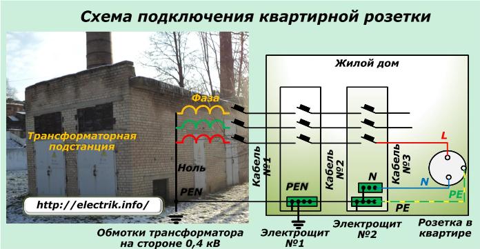
Note that in older buildings equipped with grounding system TN-C, the transition to the TN-C-S circuit may still not be completed. In this case, the splitting of the PEN conductor in the electrical distribution panel of the house will not be performed. Therefore, the sockets are connected only by a phase conductor L and a working zero N without a protective PE conductor.
Looking at the picture, you can understand that the length of the cable lines from the windings of the transformer substation to the final outlet consists of several sections and can on average have a length of hundreds of meters. In the given example, three cables, two switchboards with switching devices and several connection points are involved. In practice, there is a much larger number of connecting elements.
Such a section has a certain electrical resistance and causes voltage losses and drops even with proper and reliable installation. This value is regulated by technical standards and is determined during the preparation of the project work.
Any violations of the assembly rules of electrical circuits cause its increase and create an unbalanced mode of operation, and in some situations, an accident in the system. For this reason, the area from the winding of the transformer substation up to the outlet in the apartment is subjected to electrical measurements and the results are analyzed to adjust the technical condition.
The entire length of the mounted chain from the outlet to the transformer winding resembles an ordinary loop, and since it is formed by two conductive lines of phase and zero, it is called a phase and zero loop.
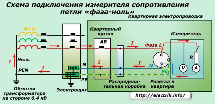
A more visual representation of its formation is given by the following simplified picture, which shows in more detail one of the methods of laying wires inside the apartment and the passage of currents through it.
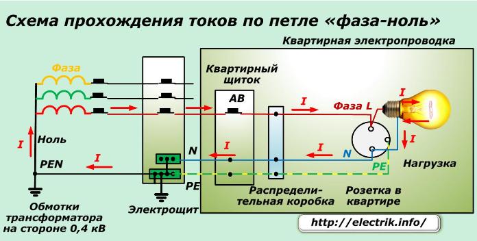
Here, for example, an on-line circuit breaker AB located inside an electrical apartment panel, contacts of a junction box to which cable wires and a load in the form of an incandescent lamp are shown are shown. Through all these elements, current flows in normal operation.
Principles of measuring phase-zero loop resistance
As you can see, the voltage from the step-down winding of the transformer substation, which creates the flow of current through the bulb connected to the socket, is supplied to the outlet via wires.In this case, some part of the voltage is lost on the resistance of the wires of the supply line.
The relationship between resistance, current and voltage drop in a circuit section is described by Ohm's famous law.
R = U / I.
Just keep in mind that we do not have a constant current, but an alternating sinusoidal one, which is characterized by vector quantities and is described by complex expressions. Its full value is affected not by one active component of the resistance, but by the reactive component, including the inductive and capacitive parts.
These patterns are described by the triangle of resistances.
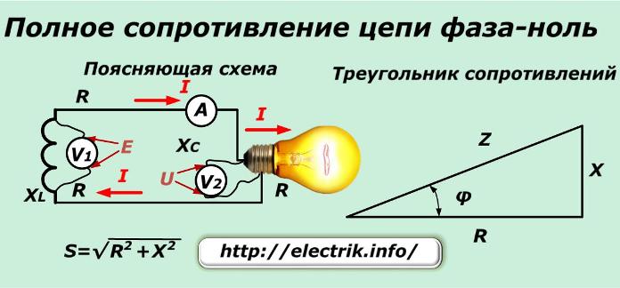
The electromotive force generated on the transformer winding creates a current that generates a voltage drop on the bulb and circuit wires. The following types of resistance are overcome:
-
active at the filament, wires, contact joints;
-
inductive from built-in windings;
-
capacitive of individual elements.
The main part of the impedance is the active part. Therefore, during installation of the circuit for an approximate assessment, it is allowed to be measured from direct voltage sources.
The total resistance S of the phase-zero loop section, taking into account the load, is determined as follows. First, the value of the EMF created on the transformer winding is recognized. Its value will accurately show the voltmeter V1.
However, access to this place is usually limited, and it is impossible to perform such a measurement. Therefore, a simplification is made - the voltmeter is inserted into the contacts of the socket of the outlet without load and the voltage reading is recorded. Then:
-
an ammeter, load and voltmeter are connected to it;
-
instrument readings are recorded;
-
calculation is in progress.
When choosing a load, you need to pay attention to it:
-
stability during measurements;
-
the possibility of generating current in a circuit of the order of 10 ÷ 20 amperes, because at lower values, installation defects may not appear.
The magnitude of the loop impedance, taking into account the connected load, is obtained by dividing the value E measured by voltmeter V1 by the current I determined by ammeter A.
Z1 = E /I = U1 / I
The load impedance is calculated by dividing the voltage drop of its section U2 by current I.
Z2 = U2 / I.
Now it remains only to exclude the load resistance Z2 from the calculated value Z1. Get the impedance of the phase-zero loop Zp. Zp = Z2-Z1.
Technological features of measurement
By amateur measuring instruments it is practically impossible to precisely determine the value of loop resistance due to the large values of their error. The work must be performed with ammeters and voltmeters of high accuracy class 0.2, and they, as a rule, are used only in electrical laboratories. In addition, they require skillful handling and frequent timing of verification in the metrological service.
For this reason, it is better to entrust the measurement to laboratory specialists. However, they are most likely to use not a single ammeter and voltmeter, but specially designed for this high-precision phase-zero loop resistance meters.

Consider their device on the example of a device called a short circuit current meter type 1824LP. How correct this term will not be judged. Most likely, it was used by marketers to attract buyers for advertising purposes. After all, this device is not able to measure short circuit currents. It only helps to calculate them after measurements during normal operation of the network.
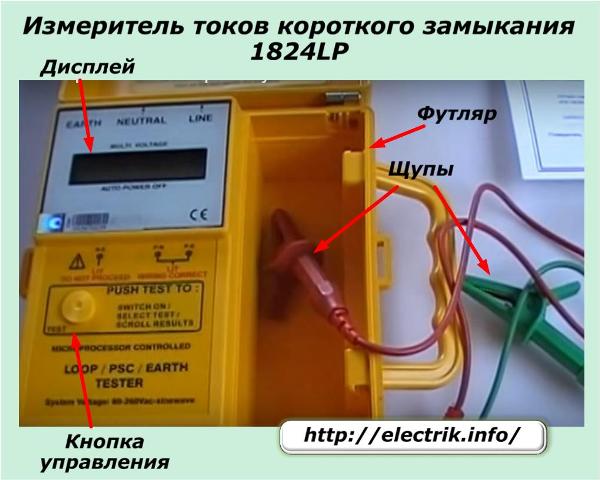
The measuring device is supplied with wires and lugs laid inside the cover. On its front panel there is one control button and a display.
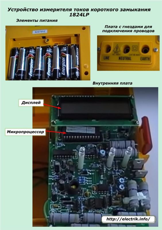
Inside, the electrical measuring circuit is fully implemented, eliminating unnecessary user manipulation. To do this, it is equipped with a load resistance R and voltage and current meters connected by pressing a button.
The batteries, internal circuit board and jacks for connecting the connecting wires are shown in the photograph.
Such devices are connected by wire probes to a power outlet and operate in automatic mode. Some of them have random access memory in which measurements are entered. They can be viewed sequentially after some time.
Technology for measuring resistance with automatic meters
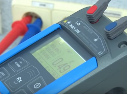
On the device prepared for operation, the connecting ends are installed in the sockets and on the reverse side they are connected to the socket contacts. The meter immediately automatically determines the voltage value and displays it in digital form. In the above example, it is 229.8 volts. After that, click on the mode switch button.
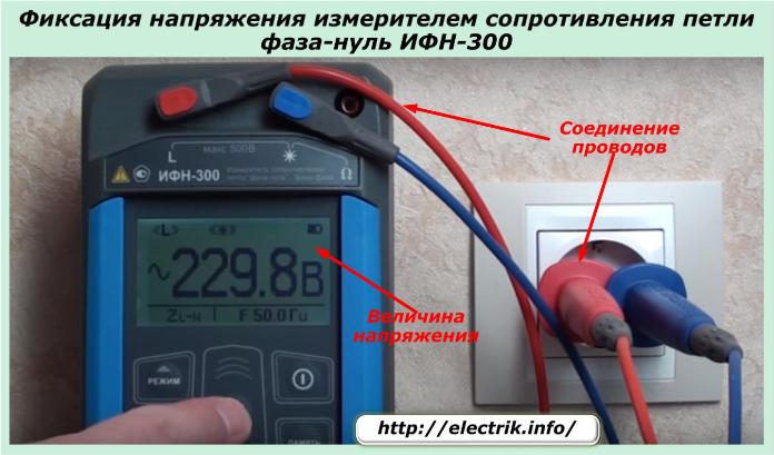
The device closes the internal contact to connect the load resistance, creating a current of more than 10 amperes in the network. After this, current measurement and calculations take place. The magnitude of the impedance of the phase-zero loop is displayed. In the photo, it is 0.61 Ohm.
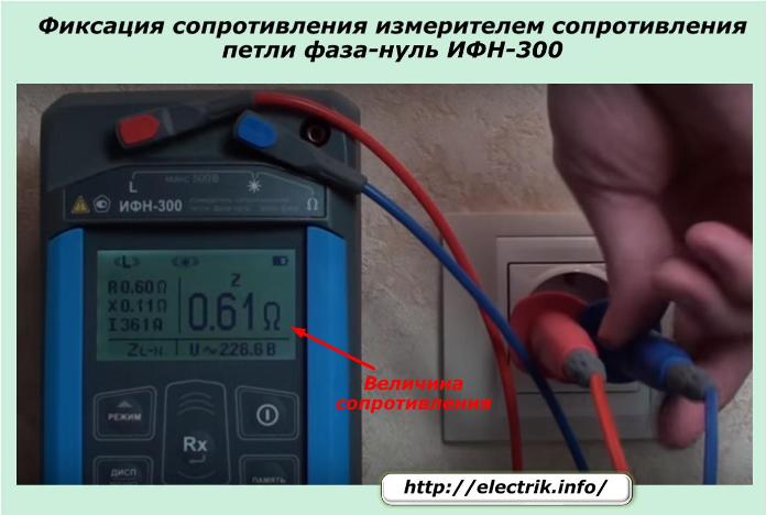
Separate meters during operation use the algorithm for calculating the short circuit current and additionally display it on the display.
Measurement Locations
The method for determining resistance shown by the two previous photos is fully applicable to wiring diagrams assembled using an outdated TN-C system. When a PE conductor is present in the wiring, it is necessary to determine its quality. This is done by connecting the device wires between the phase contact and the protective zero. There are no other differences between the method.
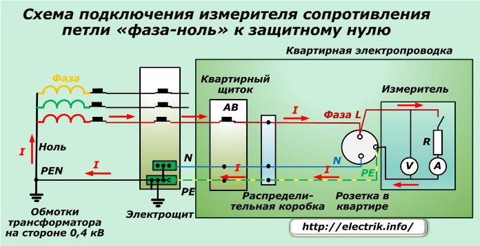
Electricians not only evaluate the resistance of the phase-zero loop at the final outlet, but often this procedure must be performed on an intermediate element, for example, a terminal block of a distribution cabinet.
Three-phase power supply systems check the condition of the circuit of each phase separately. Short circuit current may someday flow through any of them. And how they are assembled will show the measurements.
Why metering
Checking the resistance of the phase-zero loop is carried out for two purposes:
1. determining the quality of installation to identify weaknesses and errors;
2. assessment of the reliability of the selected protection.
Identification of installation quality
The method allows you to compare the measured real value of resistance with the calculated allowed by the project when planning work. If the wiring was carried out efficiently, then the measured value will meet the requirements of technical standards and will ensure safe operation.
When the calculated value of the loop is unknown, and the real is measured, then you can contact the specialists of the design organization to perform calculations and subsequent analysis of the network status. The second way is to try to figure out the tables of designers yourself, but this will require engineering knowledge.
If the loop resistance is too high, you will have to look for marriage in work. It may be:
-
dirt, corrosion on contact joints;
-
underestimated cable cross-section, for example, the use of 1.5 squares instead of 2.5;
-
low-quality execution of twists made with reduced length without welding ends;
-
the use of material for live conductors with high resistivity;
-
other reasons.
Assessment of the reliability of selected protections
The problem is solved as follows.
We know the value of the rated voltage of the network and determined the value of the loop impedance. When a metal phase short circuit occurs to zero, a single-phase short-circuit current will flow through this circuit.
Its value is determined by the formula Ikz = Unom / Zp.
Consider this issue for the impedance value, for example, at 1.47 ohms. Ikz = 220 V / 1.47 Ohm = 150A
We have determined this value. Now it remains to evaluate the quality of the choice of ratings of the protective circuit breaker installed in this chain to eliminate accidents.
Recall that PUEs require choosing an automatic machine that provides a value of 1.1 of the rated current (Inom N) for AB with instantaneous releases.In this paragraph, under N = 5, 10, 20, the characteristics of the releases of types "B", "C", "D" are used. You can read more about the features of using current-time characteristics here: Characteristics of circuit breakers
Suppose that an “C” class circuit breaker with a rated current of 16 amperes and a multiplicity of 10 is installed in the switchboard. For it, the short-circuit breaking current by an electromagnetic release must be no less than that calculated by the formula: I = 1.1x16x10 = 176 A. And we calculated 150 A.
We make 2 conclusions:
1. The current operating electromagnetic cutoff is less than what may occur in the circuit. Therefore, the circuit breaker will not be disconnected from it, and only the operation of the thermal release will occur. But its time will exceed 0.4 seconds and will not ensure safety - a high probability of a fire.
2. The circuit breaker is not installed correctly and must be replaced.
All these facts make it possible to understand why professional electricians pay special attention to the reliable assembly of electrical circuits and measure the resistance of the phase-zero loop immediately after installation, periodically during operation and if there are doubts about the correct operation of the circuit breakers.
See also at bgv.electricianexp.com
:
