Categories: Practical Electronics, Repair of household appliances
Number of views: 21344
Comments on the article: 0
Current measurement
DC current measurement
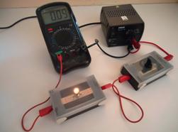 In electronic technology, it is often necessary to measure direct currents. Apparently, for this reason, many multimeters, mostly cheap, can only measure direct current. The measurement range of alternating current is in some models of multimeters, which are more expensive, but these indications can only be trusted if the current has a sinusoidal shape and the frequency does not exceed 50 Hz.
Ammeter Requirements
Any measuring device is considered good if it does not introduce distortions into the measured quantity, or rather, introduces, but as little as possible. For a voltmeter, this is a high input impedance, since it is connected in parallel with the circuit section. It is appropriate to recall here that with a parallel connection, the total resistance of the section decreases.
Ammeter is included in the break of the circuit, therefore, for him, a positive quality, unlike a voltmeter, is considered to be just a low internal resistance. Moreover, the smaller the better, especially when measuring low currents, so inherent in electronic circuits. The current measurement process is shown in Figure 1.
The diagram shows a simple electrical circuit consisting of a galvanic battery and two resistors, suitable only for conducting experiments on measuring currents. First of all, you should pay attention to the polarity of the device, it must coincide with the direction of the current, which is indicated by arrows.
The figure shows a pointer device that will not show in the opposite direction. For a digital multimeter, the direction of the current does not matter. If it is connected incorrectly, it will simply show a minus sign, and the conflict will be settled on this. Mathematicians would say that the modulus of a number is measured, it seems that is the name of the unsigned number.
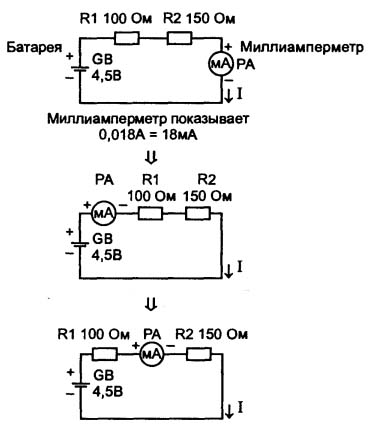
Picture 1.Current measurement process
What the ammeter will show
For such a simple circuit, it is not difficult to calculate the current, it will be 0.018A or 18mA. At the same time, the figure shows that a milliammeter in the same circuit is connected at three different points. According to the laws of physics, his readings will be exactly the same, because how many electrons "flow out" from the plus of the battery, the same number returns back, but after a "minus". And the path for all these electrons is one: these are connecting wires, resistors, and if connected, then milliammeters.
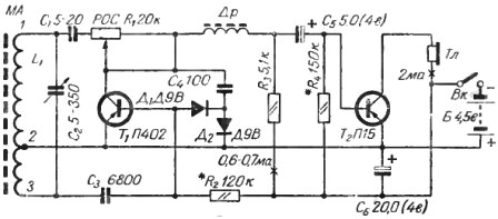
Figure 2 shows a diagram of a two-transistor receiver from the book of M.M. Rumyantsev "50 circuits of transistor receivers" (1966).
Figure 2Dual Transistor Receiver Circuit
In those days, circuits in books were accompanied by detailed descriptions and methods of their adjustment. It was often recommended to measure currents in specific sections of the circuit, usually the collector currents of transistors. Places for measuring currents were shown on the diagram with a cross. At this point, naturally, a milliammeter was connected to the gap of the conductor, and by selecting the resistor value marked with an asterisk, the current indicated immediately on the diagram was selected.
Pitfalls in measuring currents
Figures 3 and 4 show the simplest circuit, a battery, a resistor, and a multimeter. According to Ohm's law, it is easy to calculate that the current in this circuit will be
I = U / R = 1.5 / 10 = 0.15A or 150mA.
If you look closely at both figures, it turns out that the readings are different, although nothing has changed in the circuits themselves, if they can be called that. In Figure 3, the readings are fully consistent with Ohm's calculation.
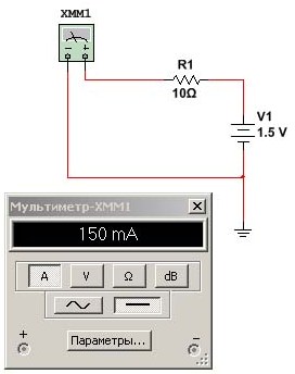
Figure 3. Measurements current in the program simulator Multisim
But in Figure 4 they became slightly lower, namely 148.515mA. The question is, why? After all, nothing has changed on the circuit, the source is the same and the resistor has not become more or less.
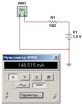
Figure 4. Measurements current in the program simulator Multisim
The fact is that any properties of the multimeter can be changed, which is done by clicking on the "Options" button.In this case, the input resistance of the ammeter was changed: in Figure 3 it was 1n & # 8486; and in Figure 4 it was increased to 100mΩ, or only 0.1Ω. This example is provided to demonstrate how the properties of a measuring instrument affect the result. In this case, an ammeter.
Let's try to increase the current 10 times in this circuit. To do this, it is enough to reduce the value of the resistor also by 10 times, then it is easy to calculate that the ammeter will show one and a half amperes. If the input impedance is taken to be 1nΩ, as in Figure 3, the result will be 1.5A, which is fully consistent with Ohm's calculation.
If using the above-mentioned button “Parameters” to make the resistance of the ammeter 0.1Ω, then on the scale of the device you can see 1,364A. Of course, 0.1Ω is a little too big for a real ammeter, and 1nΩ probably only happens in the program - the simulator can still see how the internal resistance of the device affects the measurement result. In general, making such measurements, one must immediately figure out “in the mind” at least the order of the result. But you should start with a obviously larger range on the device.
This is the case when measuring currents in a simulator program, where everything is deliberately set to achieve better results. All parts with minimal tolerances, input impedances of the devices are also ideal, the ambient temperature is 25 degrees. But, as was just shown, the parameters of devices, parts and even temperature can be set at the request of the user.
Measurements with this instrument
In real life, everything is not so smooth. Wide Resistors may have tolerances of, as a rule, ± 5, 10 and 20 percent. Of course, there are resistors with tolerances of a tenth of a percent, but they are used only where it is really necessary, and not at all in widespread use equipment near each transistor and near each microcircuit.
It is assumed that experiments on measuring currents are conducted with resistors with a 5% tolerance. Then, at the nominal value (what is written on the resistor case), for example, 10KΩ, a resistor with a resistance in the range of 9.5 ... 10.5KΩ can fall under the arm. If such a resistor is connected to a voltage source, for example 10V, then when measuring currents, you can get values in the range of 1.053 ... 0.952mA, instead of the expected 1mA. An even greater spread will be obtained when using resistors with a tolerance of 10 or 20 percent.
And absolutely amazing results can be obtained if these experiments are conducted on battery power. The circuit is exactly the same as in Figures 3 and 4. It is so simple that you can completely dispense with soldering and printed circuit boards, do everything simply with twists, or simply hold it in your hands.
Let's estimate what should turn out, what the device should show. It is known that the battery voltage is 1.5V, resistance 10Ω. Then, according to Ohm's law, I = U / R = 1.5 / 10 = 0.15A or 150mA.
In actual measurements, instead of the expected 150mA, the device showed 98.3mA. Even if we assume that the resistor is caught with a 20 percent tolerance, I = U / R = 1.5 / 12 = 0.125A or 125mA.
It will not be enough! Where did it all go? In our case, the “dead” battery turned out to be to blame. During operation, she lost part of the charge, and her internal resistance increased. Adding to the resistance of the external resistor, the internal resistance made its "feasible contribution" to the distortion of the measurement result. It was these circumstances that led to the fact that the readings of the device were, to put it mildly, very far from the expected ones.
Therefore, when taking measurements in electronic circuits, one must be extremely careful, accuracy will also not be superfluous. Qualities that are directly opposite to those just mentioned lead to disastrous results. Measuring instruments can be burned, devices that are being developed or repaired, too, and in some cases even get an electric shock. To avoid disappointment from such cases, we can once again recommend recalling safety regulations.
Boris Aladyshkin
See also at bgv.electricianexp.com
:

