Categories: Novice electricians, Industrial electrician
Number of views: 35817
Comments on the article: 2
How are devices for measuring resistance arranged and working
By their physical nature, all substances react differently to the flow of electric current through them. Some bodies pass it well and they are referred to as conductors, while others are very bad. These are dielectrics.
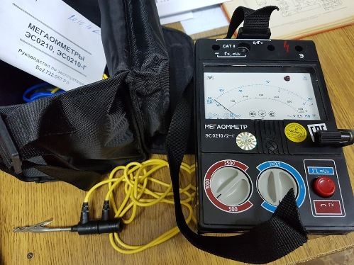
The properties of substances to counteract the flow of current are estimated by numerical expression - the value of electrical resistance. The principle of its definition was proposed by Georg Om. The unit of measure for this characteristic is named after him.
The relationship between the electrical resistance of a substance, the voltage applied to it, and the flowing electric current is called Ohm's law.
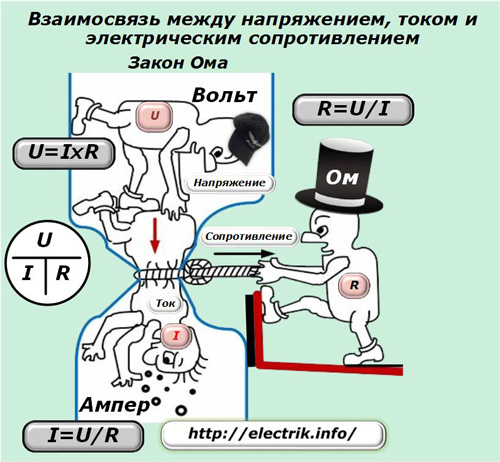
Principles of measuring electrical resistance
Based on the dependence of the three most important characteristics of electricity shown in the picture, the resistance value is determined. To do this, you must have:
1. energy source, for example battery or battery;
2. Measuring instruments of current and voltage.
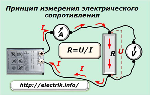
The voltage source is connected through an ammeter to the measured section, the resistance of which must be determined, and the voltage drop across the consumer is measured with a voltmeter.
Having removed the countdown of the current I with an ammeter and the voltage U with a voltmeter, the resistance value R is calculated according to Ohm's law. This simple principle allows measurements and manual calculations. However, using it in this form is difficult. For convenience, ohmmeters are created.
The design of the simplest ohmmeter
Manufacturers of measuring devices produce resistance measuring devices that work according to:
1. analogue;
2. or digital technology.
The first type of devices is called pointer due to the way information is displayed - moving the arrow relative to the initial position at the reference point on the scale.
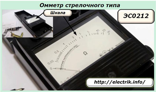
Switch type ohmmeters, as resistance measuring instruments, appeared first and continue to work successfully to the present. They are in the arsenal of tools of most electricians.
In the design of these devices:
1. all components of the above diagram are built into the housing;
2. the source produces a stabilized voltage;
3. the ammeter measures the current, but its scale is immediately calibrated in units of resistance, which eliminates the need for constant mathematical calculations;
4. wires with ends are connected to the external terminals of the case terminals, which ensure the quick creation of electrical connection with the tested element.
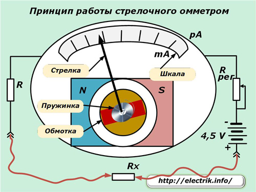
Switch devices of this class of measurement work due to their own magnetoelectric system. A wire winding is placed inside the measuring head, into which a conductive spring is connected.
In this winding from the power source, a current passes through the measured resistance Rx, limited by the resistor R to a milliamp level. It creates a magnetic field that begins to interact with the field of a permanent magnet located here, which is shown in the diagram by the N – S poles.
The sensitive arrow is fixed on the axis of the spring and, under the action of the resulting force generated from the influence of these two magnetic fields, deviates by an angle proportional to the strength of the flowing current or the value of the resistance of the conductor Rx.
The scale of the device is made in the divisions of resistance - Ohm. Due to this, the position of the arrow on it immediately indicates the desired value.
The principle of operation of a digital ohmmeter
In its pure form, digital resistance meters are available for complex work for special purposes. Mass consumer is now available wide range of combined instrumentscombining in their design the tasks of an ohmmeter, voltmeter, ammeter and other functions.
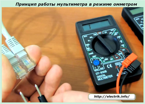
To measure the resistance, it is necessary to transfer the corresponding switches to the required operating mode of the device and connect the measuring ends to the circuit under test.
When the contacts are open, the display will show “I”, as shown in the photo. It corresponds to a larger value than the device can determine at a given sensitivity area. Indeed, in this position, he already measures the resistance of the air section between the contacts of the clamps of the connecting wires.
When the ends are mounted on a resistor or conductor, the digital ohmmeter will display the value of its resistance in real numbers.
The principle of measuring electrical resistance with a digital ohmmeter is also based on the application of Ohm's law. But, in its design, more modern technologies related to the use of:
1. appropriate sensors designed to measure current and voltage, which transmit information on digital technologies;
2. microprocessor devices that process the information received from the sensors and display them on the board in a visual form.
Each type of digital ohmmeter can have its own distinctive user settings, which should be studied before work. Otherwise, out of ignorance, you can make gross errors, because applying voltage to its input is quite common. It is manifested by the burning out of the internal elements of the circuit.
Conventional ohmmeters test and measure electrical circuits formed by wires and resistors that have relatively small electrical resistances up to several tens or thousands of ohms.
DC measuring bridges
Electrical resistance measurement devices in the form of ohmmeters are designed as portable, mobile devices. It is convenient to use them for evaluating typical, standard circuits or the continuity of individual circuits.
In laboratory conditions, where high accuracy and high-quality observance of metrological characteristics are often needed when performing measurements, other devices work - DC measuring bridges.
Electrical circuits for DC bridges
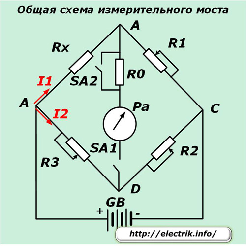
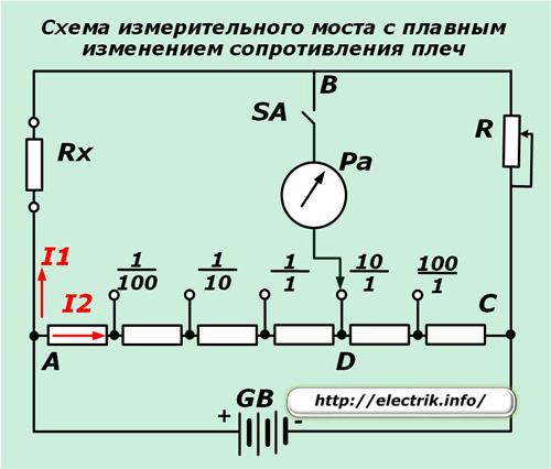
The principle of operation of such devices is based on comparing the resistances of two shoulders and creating a balance between them. The balanced mode is controlled by a control millimeter or microammeter to stop the flow of current in the diagonal of the bridge.
When the arrow of the device is set to zero, you can calculate the desired resistance Rx from the values of the standards R1, R2 and R3.
The measuring bridge circuit may have the ability to smoothly control the resistance of the standards in the shoulders or be performed in steps.
Appearance of measuring bridges
Structurally, such devices are made in a single factory building with the ability to conveniently assemble the circuit for electrical verification. Reference switching controls allow quick resistance measurements.
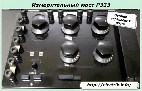
Ohmmeters and bridges are designed to measure the resistance of electric current conductors having a resistive resistance of a certain value.
Ground loop resistance meters
The need for periodic monitoring of the technical condition building ground loops caused by the conditions of their presence in the soil, which causes corrosion processes of metals. They degrade the electrical contacts of the electrodes with the soil, the conductivity and protective properties of the runoff of emergency discharges.
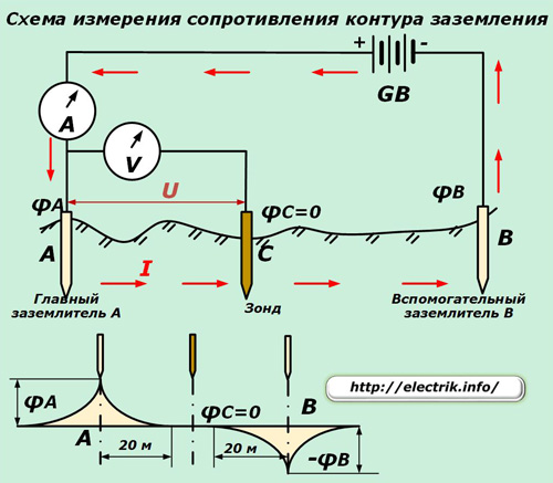
The principle of operation of devices of this type is also based on Ohm's law. The probe of the ground loop is stationary located in the ground (point C), due to which its potential is equal to zero.
At equal distances from it of about 20 meters, the same type of ground electrode system (main and auxiliary) is driven into the ground so that a stationary probe is located between them.A current from a stabilized voltage source is passed through both of these electrodes and its value is measured with an ammeter.
In the area of the electrodes between the potentials of points A and C, a voltage drop is measured with a voltmeter, caused by the flow of current I. Next, the circuit resistance is calculated by dividing U by I taking into account the correction for current losses in the main ground electrode.
If instead of an ammeter and a voltmeter, a logometer with coils of current and voltage is used, then its sensitive arrow will immediately indicate the final result in ohms, saving the user from routine calculations.
According to this principle, many brands of pointer devices work, among which the old models MC-0.8, M-416 and F-4103 are popular.
They are successfully complemented by a variety of modern resistance meters, created for such purposes with a large arsenal of additional functions.
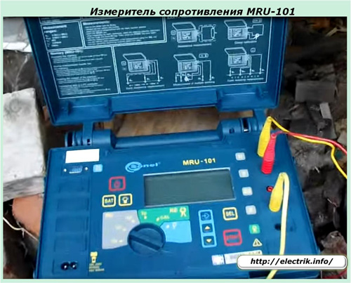
Soil resistivity measuring instruments
Using the class of devices just examined, the resistivity of the soil and various granular media is also measured. To do this, they are included in a different way.
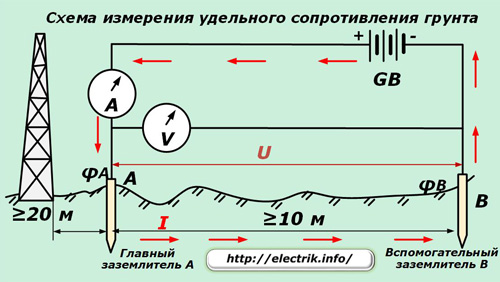
The electrodes of the main and auxiliary earthing switches are spaced a distance greater than 10 meters. Considering that the measurement accuracy can be influenced by nearby conductive objects, for example, metal pipelines, steel towers, fittings, it is permissible to approach them no less than 20 meters.
The remaining measurement rules remain the same.
The principle of measuring the resistivity of concrete and other solid media works in the same way. Special electrodes are used for them and the measurement technology changes slightly.
How are megaohmmeters arranged
Conventional ohmmeters are powered by the energy of a battery or battery - a small voltage source. Its energy is enough to create a weak electric current that reliably passes through metals, but it is not enough to create currents in dielectrics.
For this reason, an ordinary ohmmeter cannot detect most of the defects that occur in the insulation layer. For these purposes, another type of resistance measuring instruments has been specially created, which are commonly called the Megaohmmeter in the technical language. The name means:
-
mega - million, prefix;
-
Ohm - unit of measure;
-
meter - a common abbreviation of the word measure.
Appearance
Devices of this type are also pointer and digital. As an example, a megaohmmeter of the M4100 / 5 brand can be demonstrated.
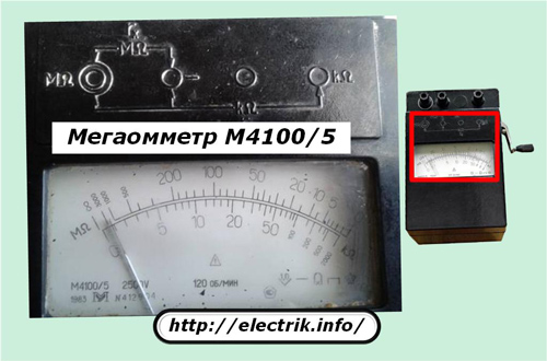
Its scale consists of two subranges:
1. MΩ - megaoms;
2. KΩ - kiloomes.
Electric circuit
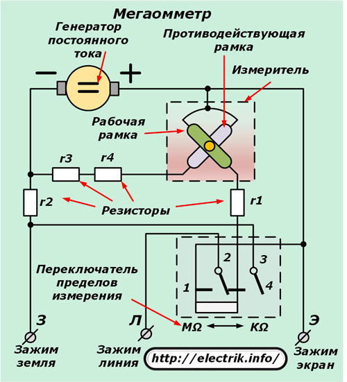
Comparing it with the circuit diagram of a conventional ohmmeter, it is easy to see that it works according to the same principles based on the application of Ohm's law.
A direct current generator acts as a voltage source, the handle of which must be evenly rotated at a certain speed of about 120 revolutions per minute. The level of high-voltage voltage issued to the circuit depends on this. This value should break through the layer of defects with reduced insulation and create a current through it, which will be displayed by mixing the arrows on the scale.
The switch of the measurement mode MΩ — KΩ switches the position of the resistor groups of the circuit, ensuring the operation of the device in one of the working subranges.
The difference between the design of a megohmmeter and a simple ohmmeter is that this device does not use two output terminals connected to the measured area, but three: Z (ground), L (line) and E (screen).
The earth and line terminals are used to measure the insulation resistance of live parts relative to earth or between different phases. The screen terminal is designed to eliminate the effect of the generated leakage currents through the insulation on the accuracy of the device.
For a large number of megaohmmeters of other models, the terminals indicate a little differently: "rx", "-", "E".But the essence of the device’s operation does not change from this, and the screen terminal is used for the same purposes.
See more about this here: How to use a megaohmmeter
Digital Megaohmmeters
Modern instruments for measuring insulation resistance of equipment operate on the same principles as their analogue switches. But they differ in a significantly larger number of functions, convenience in measurements, dimensions.
When choosing digital devices for continuous operation, their peculiarity should be taken into account: operation from an autonomous power source. In cold weather, the batteries quickly lose their working capacity and require replacement. For this reason, the work of arrow models with a hand generator remains in demand.
Safety rules when working with megaohmmeters
The minimum voltage generated by the device at the output terminals is 100 volts. It is used to check the insulation of electronic components and sensitive equipment.
Depending on the complexity and design of the electrical equipment, megaohmmeters use other voltages up to and including 2.5 kV. The most powerful devices can evaluate the insulation of high-voltage equipment of power lines.
All these works require the strict observance of safety rules, and they can be carried out only by trained specialists who have permission to work under voltage.
Typical hazards created by megaohmmeters during operation are:
-
dangerous high voltage at the output terminals, test leads, connected electrical equipment;
-
the need to prevent the action of the induced potential;
-
creating a residual charge on the circuit after performing the measurement.
When measuring the resistance of an insulation layer, a high voltage is applied between the live part and the ground loop or equipment of a different phase. On long cables, power lines, it charges a capacitance formed between different potentials. Any inept worker with his body can create a path for the discharge of this capacity and receive electric injury.
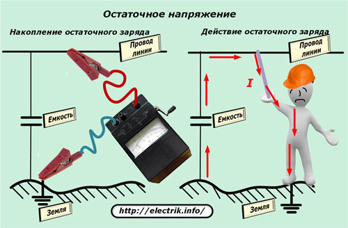
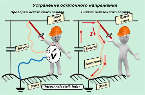
To exclude such unfortunate situations, before measuring with a megaohmmeter, they check the absence of dangerous potential on the circuit and remove it after working with the device according to a special technique.
Ohmmeters, megaohmmeters and the meters discussed above operate on direct current, they determine only the resistance.
Resistance measuring instruments in alternating current circuits
The presence of a large number of different inductive and capacitive consumers both in domestic household electrical networks and in production, including energy enterprises, creates additional energy losses due to the reactive component of the total electrical resistance. Hence the need arises for its full accounting and performance of specific measurements.
Phase-zero loop resistance meters
When a fault occurs in the electrical wiring, which leads to a shortening of the phase potential to zero, a circuit is formed along which the short circuit current flows. Its value is affected by the resistance of the wiring section from the fault location to the voltage source. It determines the magnitude of the emergency current, which must be switched off by circuit breakers.
therefore loop resistance phase zero it is necessary to carry out at the most remote point and, taking into account it, select the values of the circuit breakers.
To perform such measurements, several techniques have been developed based on:
-
voltage drop with: disconnected circuit and load resistance;
-
short circuit with reduced currents from an external source.
Measurement on the load resistance built into the device is accurate and convenient. To do this, the ends of the device are inserted into the outlet farthest from the protections.
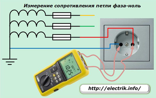
It is worth taking measurements in all outlets.Modern meters working on this method immediately show the resistance of the phase-zero loop on their scoreboard.
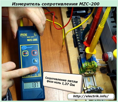
All considered devices represent only a part of devices for measuring resistance. Power engineering enterprises operate entire measuring complexes, which make it possible to constantly analyze the changing values of electrical parameters on complex high-voltage equipment and take urgent measures to eliminate the arising malfunctions.
See also at bgv.electricianexp.com
:
