Categories: Repair of household appliances, Electric motors and their application
Number of views: 55467
Comments on the article: 2
Types and arrangement of revolutions of collector engine speed
Collector motors can often be found in household electrical appliances and in power tools: a washing machine, grinder, drill, vacuum cleaner, etc. Which is not at all surprising, because the collector motors allow you to get both high revolutions and high torque (including high starting torque ) - which is what is needed for most power tools.
In this case, the collector motors can be powered by both direct current (in particular, rectified) and alternating current from a household network. To control the rotational speed of the rotor of the collector motor, speed regulators are used, and they will be discussed in this article.
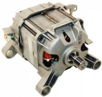
To begin with, recall the device and the principle of the collector motor. The collector motor necessarily includes the following parts: rotor, stator and brush-commutator switching unit. When power is supplied to the stator and the rotor, their magnetic fields begin to interact, and the rotor eventually rotates.
Power is supplied to the rotor through graphite brushes that fit tightly to the collector (to the collector lamellas). To change the direction of rotation of the rotor, it is necessary to change the phasing of the voltage on the stator or on the rotor.
The rotor and stator windings can be powered from different sources or can be connected in parallel or in series with each other. So distinguished are the collector motors of parallel and series excitation. Namely, sequential excitation collector motors can be found in most household electrical appliances, since such an inclusion makes it possible to obtain an engine that is resistant to overloads.
Speaking of speed controllers, first of all, let us dwell on the simplest thyristor (triac) circuit (see below). This solution is used in vacuum cleaners, washing machines, grinders, and shows high reliability when working in AC circuits (especially from a household network).
This scheme works quite simply: on each period of the mains voltage capacitor charged through a resistor to the voltage of the unlocking of the dinistor connected to the control electrode of the main key (triac), after which triac opens and passes current to the load (to the collector motor).
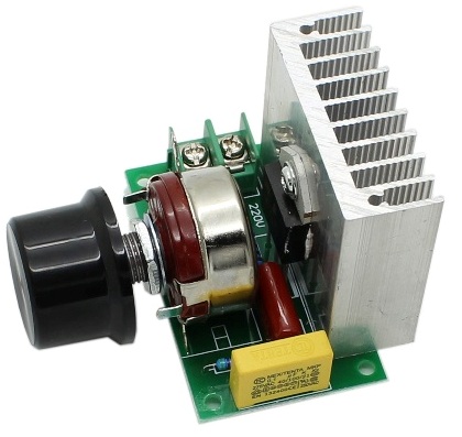
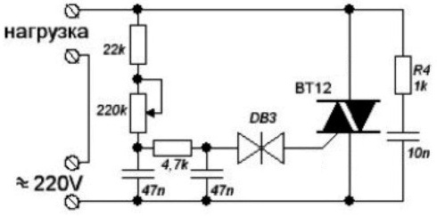
By adjusting the charging time of the capacitor in the control circuit of the opening of the triac, regulate the average power supplied to the engine, respectively, regulate the speed. This is the simplest regulator without current feedback.
Triac circuit is similar to the usual dimmer for adjusting the brightness of incandescent lamps, there is no feedback in it. In order for current feedback to appear, for example, to maintain acceptable power and prevent overloads, additional electronics are needed. But if you consider options from simple and non-simple schemes, then a triac circuit follows a triac circuit.
The rheostat circuit allows you to effectively control the speed, but leads to the dissipation of a large amount of heat. It requires a radiator and efficient heat dissipation, which means energy losses and low efficiency in the end.
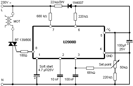
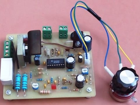
Regulator circuits are more efficient on special thyristor control circuits or at least on an integral timer. Switching the load (collector motor) on alternating current is carried out by a power transistor (or thyristor), which opens and closes one or more times during each period of the network sinusoid. This regulates the average power supplied to the engine.
The control circuit is powered by 12 volts of direct voltage from its own source or from a 220 volt network through a quenching circuit.Such schemes are suitable for controlling powerful engines.
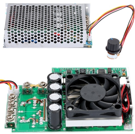
The regulation principle with DC chips is of course PWM - Pulse Width Modulation. The transistor, for example, opens with a strictly specified frequency of several kilohertz, but the duration of the open state is adjustable. So, rotating the handle of a variable resistor, set the rotational speed of the rotor of the collector motor. This method is convenient for keeping small revolutions of the collector engine under load.
Better control - this is direct current regulation. When the PWM operates at a frequency of about 15 kHz, by adjusting the pulse width, the voltage is controlled at approximately the same current. Say, by regulating a constant voltage in the range from 10 to 30 volts, they get different revolutions at a current of about 80 amperes, achieving the required average power.
If you want to make a simple regulator for a collector motor with your own hands without any special requests for feedback, then you can choose a circuit on a thyristor. All you need is a soldering iron, capacitor, dinistor, thyristor, a pair of resistors and wires.
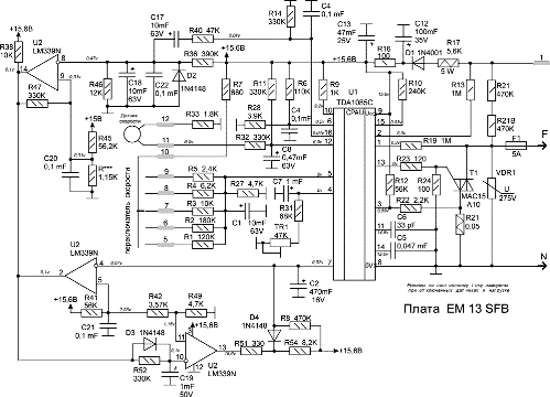
If you need a better controller with the ability to maintain stable speed under a dynamic load, take a closer look at the feedback controllers that can process the signal from the tachogenerator (speed sensor) of the collector motor, as is done for example in washing machines.
See also on this topic:PWM - 555 engine speed controllers
See also at i.electricianexp.com
:

