Categories: Interesting Facts, Practical Electronics
Number of views: 231,928
Comments on the article: 9
Capacitors: purpose, device, principle of operation
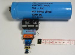 In all radio and electronic devices, except transistors and microcircuits, capacitors are used. In some circuits there are more of them, in others less, but there are practically no electronic circuits without capacitors.
In this case, capacitors can perform a variety of tasks in devices. First of all, these are containers in the filters of rectifiers and stabilizers. With the help of capacitors, a signal is transmitted between the amplifier stages, low and high frequency filters are built, time intervals in the time delays are set, and the oscillation frequency in various generators is selected.
Capacitors lead from leiden bankswhich in the middle of the 18th century was used in their experiments by the Dutch scientist Peter van Mushenbrook. He lived in the city of Leiden, so it is easy to guess why this bank was called.
Actually, this was an ordinary glass jar, lined inside and outside with a tin foil - staniol. It was used for the same purposes as modern aluminum, but then aluminum was not yet open.
The only source of electricity in those days was an electrophore machine, capable of developing a voltage of up to several hundred kilovolts. It was from her that they charged a Leyden jar. In the textbooks of physics, a case is described when Mushenbrook discharged his can through a chain of ten guards holding hands.
At that time, no one knew that the consequences could be tragic. The blow turned out to be quite sensitive, but not fatal. It didn’t come to this, because the capacity of the Leyden jar was insignificant, the impulse turned out to be very short-lived, so the discharge power was small.
How is the capacitor
The device of the capacitor is practically no different from the Leyden jar: all the same two plates, separated by a dielectric. This is how capacitors are depicted on modern electrical circuits. Figure 1 shows a schematic structure of a flat capacitor and the formula for its calculation.
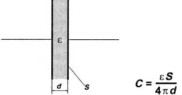
Figure 1. Flat capacitor device
Here S is the plate area in square meters, d is the distance between the plates in meters, C is the capacitance in farads, ε is the dielectric constant of the medium. All values included in the formula are indicated in the SI system. This formula is valid for the simplest flat capacitor: you can simply place two metal plates next to them, from which conclusions are drawn. Air can serve as a dielectric.
From this formula it can be understood that the capacitor is larger, the greater the area of the plates and the smaller the distance between them. For capacitors with a different geometry, the formula may be different, for example, for the capacitance of a single conductor or electric cable. But the dependence of the capacitance on the area of the plates and the distance between them is the same as that of a flat capacitor: the larger the area and the smaller the distance, the greater the capacitance.
In fact, the plates are not always made flat. For many capacitors, for example, metal, the plates are aluminum foil rolled together with a paper dielectric in a tight ball, in the shape of a metal case.
To increase the electric strength, thin capacitor paper is impregnated with insulating compositions, most often transformer oil. This design allows you to make capacitors with a capacity of up to several hundred microfarads. Capacitors with other dielectrics are similarly arranged.
The formula does not contain any restrictions on the area of the plates S and the distance between the plates d.If we assume that the plates can be spread very far, and at the same time make the area of the plates quite insignificant, then some capacity, albeit small, will still remain. This reasoning suggests that even just two conductors located in the neighborhood have an electric capacitance.
This circumstance is widely used in high-frequency technology: in some cases, capacitors are made simply in the form of printed circuit tracks, or even just two wires twisted together in polyethylene insulation. Ordinary wire-noodles or cable also have a capacity, and with increasing length it increases.
In addition to capacitance C, any cable also has resistance R. Both of these physical properties are distributed along the length of the cable, and when transmitting pulsed signals, they work as an integrating RC - chain, shown in Figure 2.

Figure 2
In the figure, everything is simple: here is the circuit, here is the input signal, but here it is at the output. The impulse is distorted beyond recognition, but this is done on purpose, for which the circuit is assembled. In the meantime, we are talking about the effect of the cable capacitance on the pulse signal. Instead of an impulse, such a “bell” will appear on the other end of the cable, and if the impulse is short, then it may not reach the other end of the cable at all, it’s completely gone.
Historical fact
Here it is quite appropriate to recall the story of how the transatlantic cable was laid. The first attempt in 1857 failed: the telegraph points - dashes (rectangular pulses) were distorted so that nothing could be disassembled at the other end of the 4000 km line.
A second attempt was made in 1865. By this time, the English physicist W. Thompson had developed the theory of data transmission over long lines. In the light of this theory, the cable routing turned out to be more successful, we managed to receive signals.
For this scientific feat, Queen Victoria granted the scientist the knighthood and the title of Lord Kelvin. That was the name of the small city on the coast of Ireland, where cable laying began. But this is just a word, and now we return to the last letter in the formula, namely, to the dielectric constant of the medium ε.
A little bit about dielectrics
This ε is in the denominator of the formula, therefore, its increase will entail an increase in capacity. For most dielectrics used, such as air, lavsan, polyethylene, fluoroplastic, this constant is almost the same as that of vacuum. But at the same time, there are many substances whose dielectric constant is much higher. If the air condenser is filled with acetone or alcohol, then its capacity will increase every 15 ... 20.
But such substances, in addition to high ε, also have a sufficiently high conductivity, therefore such a capacitor will not hold a charge well, it will quickly discharge through itself. This harmful phenomenon is called leakage current. Therefore, special materials are being developed for dielectrics that, with a high specific capacitance of capacitors, provide acceptable leakage currents. This explains the diversity of types and types of capacitors, each of which is designed for specific conditions.
Electrolytic capacitor
The largest specific capacity (capacity / volume ratio) electrolytic capacitors. The capacity of "electrolytes" reaches up to 100,000 microfarads, and the operating voltage is up to 600V. Such capacitors work well only at low frequencies, most often in filters of power supplies. Electrolytic capacitors are switched on in polarity.
The electrodes in such capacitors are a thin film of metal oxide, so often these capacitors are called oxide. A thin layer of air between such electrodes is not a very reliable insulator, therefore, an electrolyte layer is introduced between the oxide plates. Most often these are concentrated solutions of acids or alkalis.
Figure 3 shows one of these capacitors.
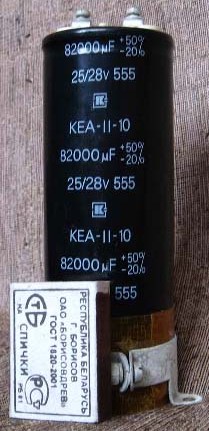
Figure 3. Electrolytic capacitor
To evaluate the size of the capacitor, a simple matchbox was photographed next to it. In addition to a sufficiently large capacity in the figure, you can also see the percentage tolerance: no less than 70% of the nominal.
In those days when computers were large and called computers, such capacitors were in drives (in the modern HDD). The information capacity of such drives can now only cause a smile: 5 megabytes of information were stored on two disks with a diameter of 350 mm, and the device itself weighed 54 kg.
The main purpose of the supercapacitors shown in the figure was the withdrawal of magnetic heads from the working area of the disk during a sudden power outage. Such capacitors could store a charge for several years, which was tested in practice.
A little lower with electrolytic capacitors will be offered to do some simple experiments to understand what a capacitor can do.
To work in AC circuits, non-polar electrolytic capacitors are produced, that's just getting them for some reason is very difficult. In order to somehow get around this problem, ordinary polar "electrolytes" include counter-sequential: plus-minus-minus-plus.
If the polar electrolytic capacitor is included in the alternating current circuit, then it will first heat up, and then an explosion will be heard. Domestic old capacitors scattered in all directions, while imported ones have a special device that avoids loud shots. This is usually either a cross notch on the bottom of the capacitor, or a hole with a rubber stopper located in the same place.
They do not like electrolytic capacitors of increased voltage, even if the polarity is observed. Therefore, you should never put "electrolytes" in a circuit where a voltage close to the maximum for a given capacitor is expected.
Sometimes in some, even reputable forums, beginners ask the question: “The capacitor 470µF * 16V is indicated on the diagram, and I have 470µF * 50V, can I put it?” Yes, of course you can, but the reverse replacement is unacceptable.
Capacitor can store energy
To deal with this statement, a simple diagram shown in Figure 4 will help.
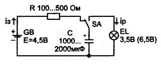
Figure 4. Circuit with capacitor
The protagonist of this circuit is an electrolytic capacitor C with a sufficiently large capacity so that the charge-discharge processes proceed slowly, and even very clearly. This makes it possible to observe the operation of the circuit visually using a conventional light from a flashlight. These lights have long given way to modern LEDs, but bulbs for them are still being sold. Therefore, it is very easy to assemble a circuit and conduct simple experiments.
Maybe someone will say: “Why? After all, everything is obvious, and even if you read the description ... ” There seems to be nothing to argue here, but any, even the simplest thing, remains in the head for a long time if its understanding came through hands.
So, the circuit is assembled. How does she work?
In the position of the switch SA, shown in the diagram, the capacitor C is charged from the power source GB through the resistor R in the circuit: + GB __ R __ SA __ C __ -GB. The charging current in the diagram is shown by an arrow with the index iз. The process of charging a capacitor is shown in Figure 5.
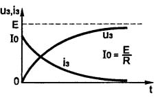
Figure 5. Capacitor Charge Process
The figure shows that the voltage on the capacitor increases along a curve, in mathematics called the exponent. The charge current directly mirrors the charge voltage. As the voltage across the capacitor rises, the charge current becomes less and less. And only at the initial moment corresponds to the formula shown in the figure.
After some time, the capacitor will be charged from 0V to the voltage of the power source, in our circuit to 4.5V. The whole question is, how is it time to determine how long to wait, when will the capacitor charge?
Tau time constant τ = R * C
In this formula, the resistance and capacitance of a series-connected resistor and capacitor are simply multiplied.If, without neglecting the SI system, substitute the resistance in Ohms, the capacitance in Farads, then the result will be in seconds. It is this time that is needed for the capacitor to charge up to 36.8% of the voltage of the power source. Accordingly, for a charge of almost 100%, a time of 5 * τ will be required.
Often, neglecting the SI system, the resistance in Ohms is substituted into the formula, and the capacitance is in microfarads, then the time will turn out in microseconds. In our case, it is more convenient to get the result in seconds, for which you just have to multiply the microseconds by a million, or, more simply put, move the comma six characters to the left.
For the circuit shown in Figure 4, with a capacitor of 2000 μF and a resistor resistance of 500 Ω, the time constant will be τ = R * C = 500 * 2000 = 1,000,000 microseconds or exactly one second. Thus, you will have to wait about 5 seconds until the capacitor is fully charged.
If, after the specified time has elapsed, the switch SA is turned to the right position, then the capacitor C is discharged through the EL bulb. At this moment, a short flash will occur, the capacitor will discharge and the light will go out. The direction of discharge of the capacitor is shown by an arrow with the index ip. The discharge time is also determined by the time constant τ. The discharge graph is shown in Figure 6.
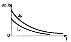
Figure 6. Capacitor discharge graph
Capacitor does not pass direct current
To verify this statement, an even simpler scheme, shown in Figure 7, will help.

Figure 7. Circuit with a capacitor in the DC circuit
If you close the switch SA, then a short flash of the bulb will follow, which indicates that the capacitor C is charged through the bulb. The charge graph is also shown here: at the moment the switch closes, the current is maximum, as the capacitor charges, it decreases, and after a while it stops completely.
If the capacitor is of good quality, i.e. with a small leakage current (self-discharge), the repeated closure of the switch will not lead to a flash. To get another flash, the capacitor will have to be discharged.
Capacitor in power filters
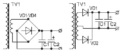
The capacitor is usually placed after the rectifier. Most often, rectifiers are made half-wave. The most common rectifier circuits are shown in Figure 8.
Figure 8. Rectifier circuits
Half-wave rectifiers are also used quite often, as a rule, in cases where the load power is insignificant. The most valuable quality of such rectifiers is simplicity: only one diode and transformer winding.
For a half-wave rectifier, the capacitance of the filter capacitor can be calculated by the formula
C = 1,000,000 * Po / 2 * U * f * dU, where C is the capacitor μF, Po is the load power W, U is the voltage at the rectifier output V, f is the frequency of the AC voltage Hz, dU is the ripple amplitude V.
A large number in the numerator of 1,000,000 converts the capacitance of the capacitor from system Farads to microfarads. The two in the denominator represents the number of half-periods of the rectifier: for a half-wave in its place, a unit will appear
C = 1,000,000 * Po / U * f * dU,
and for a three-phase rectifier, the formula will take the form C = 1,000,000 * Po / 3 * U * f * dU.
Supercapacitor - Ionistor
Recently, a new class of electrolytic capacitors, the so-called ionistor. In its properties, it is similar to a battery, however, with several limitations.
The ionistor charges to the rated voltage in a short time, literally in a few minutes, so it is advisable to use it as a backup power source. In fact, the ionistor is a non-polar device, the only thing that determines its polarity is charging at the factory. In order not to confuse this polarity in the future, it is indicated by the + sign.
An important role is played by the operating conditions of the ionistors. At a temperature of 70˚C at a voltage of 0.8 of the nominal guaranteed durability of not more than 500 hours.If the device will operate at a voltage of 0.6 from the nominal, and the temperature does not exceed 40 degrees, then proper operation is possible for 40,000 hours or more.
The most common ionistor applications are backup power sources. These are mainly memory chips or electronic clocks. In this case, the main parameter of the ionistor is a low leakage current, its self-discharge.
Quite promising is the use of ionistors in conjunction with solar panels. It also affects non-criticality to the condition of the charge and an almost unlimited number of charge-discharge cycles. Another valuable property is that the ionistor is maintenance free.
So far it has turned out to tell how and where electrolytic capacitors work, and mainly in DC circuits. The operation of capacitors in AC circuits will be described in another article - Capacitors for AC electrical installations.
Boris Aladyshkin
P.S. An interesting use case for capacitors: capacitor welding
See also at bgv.electricianexp.com
:

