Categories: Practical Electronics, All about LEDs
Number of views: 91676
Comments on the article: 4
LED brightness control
 In some cases, for example, in flashlights or home lighting fixtures, it becomes necessary to adjust the brightness of the glow. It would seem that it’s easier: just change the current through the LED, increasing or decreasing resistance limiting resistor. But in this case, a significant part of the energy will be spent on the limiting resistor, which is completely unacceptable with autonomous power supply from batteries or accumulators.
In addition, the color of the LEDs will change: for example, white when the current is lower than the nominal (for most LEDs 20mA) will have a slightly greenish tint. Such a color change in some cases is completely useless. Imagine that these LEDs illuminate the screen of a TV or computer monitor.
The principle of PWM - regulation
In these cases, apply PWM - regulation (pulse width). Its meaning is that Light-emitting diode periodically lights up and goes out. At the same time, the current remains nominal throughout the entire flash time, therefore, the spectrum of the glow is not distorted. If the LED is white, then green shades will not appear.
In addition, with this method of power control, energy losses are minimal, the efficiency of PWM-controlled circuits is very high, reaching over 90 percent.
The principle of PWM control is quite simple, and is shown in Figure 1. A different ratio of the time of the lit and extinguished state in the eye is perceived as different brightness: like in a movie - separately shown alternately frames are perceived as a moving image. It all depends on the frequency of the projection, which will be discussed a bit later.

Figure 1. The principle of PWM regulation
The figure shows the signal diagrams at the output of the PWM control device (or a master oscillator). Zero and one are indicated by logical levels: logical unit (high level) causes the LED to glow, logical zero (low level), respectively, extinction.
Although everything can be the other way around, since everything depends on the circuitry of the output key, the LED can be turned on low and off, just high. In this case, the physically logical unit will have a low voltage level, and the logical zero will be high.
In other words, a logical unit causes the inclusion of some event or process (in our case, LED illumination), and a logical zero should disable this process. That is, not always a high level at the output of a digital microcircuit is a LOGIC unit, it all depends on how a particular circuit is built. This is for information. But for now, we assume that the key is controlled by a high level, and it simply cannot be otherwise.
Frequency and width of control pulses
It should be noted that the pulse repetition period (or frequency) remains unchanged. But, in general, the pulse frequency does not affect the brightness of the glow, therefore, there are no special requirements for the stability of the frequency. Only the duration (WIDTH), in this case, of a positive pulse changes, due to which the whole mechanism of pulse-width modulation works.
The duration of the control pulses in Figure 1 is expressed in %%. This is the so-called "fill factor" or, in English terminology, DUTY CYCLE. It is expressed as the ratio of the duration of the control pulse to the pulse repetition period.
In Russian terminology is usually used "Duty cycle" - the ratio of the period to the time pulsea. Thus, if the fill factor is 50%, then the duty cycle will be 2.There is no fundamental difference here, therefore, you can use any of these values, to whom it is more convenient and understandable.
Here, of course, one could give formulas for calculating the duty cycle and DUTY CYCLE, but in order not to complicate the presentation, we will do without formulas. In extreme cases, Ohm's law. There is nothing to be done: "You do not know Ohm's law, stay at home!" If anyone is interested in these formulas, then they can always be found on the Internet.
PWM frequency for dimmer
As mentioned above, no special requirements are imposed on the stability of the PWM pulse frequency: well, it “floats” a bit, and okay. Such frequency instability, by the way, is quite large, PWM controllers have based on the integrated timer NE555that does not interfere with their use in many designs. In this case, it is only important that this frequency does not fall below a certain value.
And what should be the frequency, and how unstable can it be? Do not forget that we are talking about dimmers. In film technology, the term "critical flicker frequency" exists. This is the frequency at which individual pictures displayed one after another are perceived as a moving image. For the human eye, this frequency is 48Hz.
It is for this reason that the frequency of shooting on film was 24 frames / sec (television standard 25 frames / sec). To increase this frequency to critical, film projectors use a two-bladed shutter (shutter) that twice overlaps each displayed frame.
In amateur narrow-film 8mm projectors, the projection frequency was 16 frames / sec, so the shutter had as many as three blades. The same purpose in television is served by the fact that the image is displayed in half frames: first even, and then odd lines of the image. The result is a flicker frequency of 50Hz.
The LED operation in PWM mode is a separate flash of adjustable duration. In order for these flashes to be perceived by the eye as a continuous glow, their frequency must be no less than critical. As many as you want, but not in any way below. This factor should be considered when creating PWM - regulators for fixtures.
By the way, just as an interesting fact: the scientists somehow determined that the critical frequency for the bee's eye is 800Hz. Therefore, the bee sees the movie on the screen as a sequence of individual images. In order for her to see a moving image, the projection frequency will need to be increased to eight hundred half frames per second!
Functional diagram of a PWM controller
To control the actual LED is used transistor key stage. Recently, the most widely used for this purpose transistors mosfet, allowing you to commute significant power (the use of conventional bipolar transistors for these purposes is considered simply indecent).
Such a need (a powerful MOSFET transistor) arises with a large number of LEDs, for example, with using LED strip, which will be discussed later. If the power is low - when using one - two LEDs, you can use the keys on low-power bipolar transistors, and if possible, connect the LEDs directly to the outputs of the microcircuits.
Figure 2 shows the functional diagram of the PWM controller. As a control element, the resistor R2 is conventionally shown in the diagram. By rotating its handle, it is possible to change the duty cycle of the control pulses within the required limits, and, consequently, the brightness of the LEDs.

Figure 2. Functional diagram of a PWM controller
The figure shows three chains of series-connected LEDs with limiting resistors. Approximately the same connection is used in LED strips. The longer the tape, the more LEDs, the greater the current consumption.
It is in these cases that powerful regulators on transistors MOSFET, the permissible drain current of which should be slightly larger than the current consumed by the tape. The latter requirement is fulfilled quite easily: for example, the IRL2505 transistor has a drain current of about 100A, a drain voltage of 55V, while its size and price are attractive enough for use in various designs.
PWM master oscillators
A microcontroller (most often in industrial conditions), or a circuit made on microcircuits of a small degree of integration, can be used as a PWM master oscillator. If at home it is supposed to make a small amount of PWM regulators, but there is no experience in creating microcontroller devices, then it is better to make a regulator on what is now at hand.
This can be a logic chip series K561, an integrated timer NE555as well as specialized microchips designed for switching power supplies. In this role, you can even make work operational amplifierhaving assembled an adjustable generator on it, but this is, perhaps, “out of love for art”. Therefore, only two schemes will be considered below: the most common on the 555 timer, and on the UC3843 UPS controller.
Scheme of the master oscillator on the timer 555

Figure 3. Scheme of the master oscillator
This circuit is a regular square-wave generator whose frequency is set by capacitor C1. The capacitor is charged through the circuit "Output - R2 - RP1-C1 - common wire". In this case, the output must have a high level voltage, which is equivalent to the fact that the output is connected to the plus pole of the power source.
The capacitor is discharged through the circuit "C1 - VD2 - R2 - Output - common wire" at a time when the output is low voltage, the output is connected to a common wire. This difference in the paths of the charge — the discharge of the time-setting capacitor — provides pulses with an adjustable width.
It should be noted that diodes, even of the same type, have different parameters. In this case, their electric capacitance plays a role, which changes under the influence of voltage on the diodes. Therefore, along with a change in the duty cycle of the output signal, its frequency also changes.
The main thing is that it does not become less than the critical frequency, which was mentioned just above. Otherwise, instead of a uniform glow with different brightness, individual flashes will be visible.
Approximately (again, the diodes are to blame), the frequency of the generator can be determined by the formula shown below.
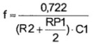
The frequency of the PWM generator on the timer 555.
If the capacitor capacitance is substituted in the formula in farads and the resistance is in Ohms, then the result should be in Hz Hz: there is no getting anywhere from the SI system! It is understood that the variable resistor RP1 engine is in the middle position (in the formula RP1 / 2), which corresponds to the output signal of the meander shape. In Figure 2, this is exactly the part where the pulse duration of 50% is indicated, which is equivalent to a signal with a duty cycle of 2.
PWM master oscillator on UC3843 chip
Its circuit is shown in Figure 4.

Figure 4. Scheme of the PWM master oscillator on the UC3843 chip
The UC3843 chip is a PWM control controller for switching power supplies and is used, for example, in ATX format computer sources. In this case, the typical scheme of its inclusion is slightly changed in the direction of simplification. To control the width of the output pulse, a regulating voltage of positive polarity is fed to the input of the circuit, then a pulse-width-modulated PWM signal is output.
In the simplest case, the regulatory voltage can be applied using a variable resistor with a resistance of 22 ... 100K. If necessary, the control voltage can be obtained, for example, from an analog light sensor made on a photoresistor: the darker the window, the brighter the room.
The control voltage acts on the PWM output, so that when it decreases, the width of the output pulse increases, which is not at all surprising.After all, the initial purpose of the UC3843 chip is to stabilize the voltage of the power supply: if the output voltage drops, and with it the regulating voltage, then you need to take measures (increase the width of the output pulse) to slightly increase the output voltage.
Regulatory voltage in power supplies is generated, as a rule, using zener diodes. Most often it is TL431 or the like.
With the values of parts indicated on the diagram, the generator frequency is about 1 KHz, and unlike the generator on the 555 timer, it does not “float” when the duty cycle of the output signal changes — concern about the constancy of the frequency of switching power supplies.
To regulate significant power, for example, an LED strip, the key stage on the MOSFET transistor should be connected to the output, as shown in Figure 2.
It would be possible to talk more about PWM regulators, but for now let us dwell on this, and in the next article we will consider various ways of connecting LEDs. After all, not all methods are equally good, there are those that should be avoided, and there are just enough errors when connecting LEDs.
Continuation of the article:Good and bad LED wiring patterns
Boris Aladyshkin
See also at bgv.electricianexp.com
: