Categories: Electrician at home, How does it work, Sockets and switches
Number of views: 307,520
Comments on the article: 22

Dimmer device and circuit
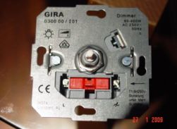
 

Dimmer device and circuitIn this article, we will consider a device that is sold in electrical goods stores as a dimmer control. It's about a dimmer. Title "Dimmer" came from the English verb "to dim" - to darken, become dull. In other words, the dimmer can be adjusted lamp brightness. Moreover, it is remarkable that the power consumption decreases proportionally.

The simplest dimmers have one rotary knob for adjustment, and two terminals for connection, and are used to adjust the brightness of incandescent and halogen lamps. Recently, dimmers have also appeared to adjust the brightness of fluorescent lamps.

Previously, rheostats whose power was not less than the load power were used to adjust the brightness of incandescent lamps. Moreover, with a decrease in brightness, the remaining power was not saved in any way, but was dissipated uselessly in the form of heat on a rheostat. At the same time, no one spoke about saving, it simply did not exist. And such devices were used where it really was only necessary to adjust the brightness - for example, in theaters.

So it was before the advent of wonderful semiconductor devices - a dinistor and a triac (symmetric thyristor). See: How the simistor is arranged and works. In English practice, other names are accepted - diac and triac. Based on these details and work modern dimmers.
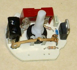
Dimmer device
Dimmer device

Dimmer connection

The circuit for switching on the dimmer is impossibly simple - you can’t imagine any easier way. It turns on in the same way as a conventional switch - into the open circuit of the load supply, that is, the lamp. In terms of installation dimensions and mounting, the dimmer is identical to the switch. Therefore, it can be installed in the same way as a switch in a mounting box, and the installation of a dimmer is no different from the installation of a conventional switch (How to replace the light switch) The only condition that the manufacturer makes is to observe the connection of the leads to the phase and to the load.

All the dimmers that are currently on sale can be divided into 2 groups - rotary, or rotary (with a regulator - potentiometer) and electronic, or push-button, with buttons.
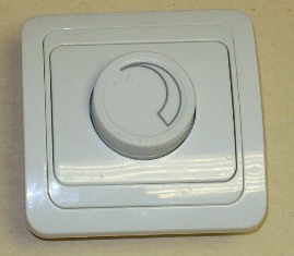
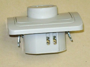
Rotary dimmer
Rotary dimmer

Rotary dimmer

When adjusting (dimming) the potentiometer knob, the brightness depends on the angle of rotation. The push-button dimmer in the sense of control flexibility is more flexible. You can connect several buttons in parallel, and control the dimmer from any number of places. Of course, this is theoretically, in practice, the number of control places is limited to 3-4, and the maximum length of wires is about 10 meters, and the circuit can be critical to interference and interference. Therefore, we must strictly follow the manufacturer's recommendations for installation.

There are also remote dimmers controlled via radio or infrared. See: Remote lighting control.

The price for dimmers with a regulator and buttons differs by an order of magnitude, because a button dimmer (for example, a Legrand dimmer) is usually assembled with microcontroller application. Therefore, rotary dimmers are much more common, which we will consider below.


The device and circuit rotary dimmer

The rotary dimmer device is very simple, but may differ from different manufacturers. In this case, the main difference is in the quality of assembly and components.

The circuit of triac regulators is basically the same everywhere, it differs only in the presence of additional parts for more stable operation at low "output" voltages and for smooth regulation.
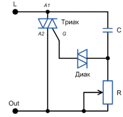
Simplified Dimmer Circuit

Simplified Dimmer Circuit

The principle of operation of the dimmer circuit is as follows. For the lamp to light up, it is necessary for the triac to pass a current through itself. This will happen when a certain voltage appears between the electrodes of the triac A1 and G. This is how it appears.

At the beginning of the positive half-wave, the capacitor begins to charge through the potentiometer R. It is clear that the charge speed depends on the value of R. In other words, the potentiometer changes the phase angle. When the voltage across the capacitor reaches a value sufficient to open the triac and dinistor, the triac opens.

In other words, its resistance becomes very small, and the bulb burns to the end of the half-wave. The same thing happens with the negative half-wave, since the diac and triac are symmetrical devices, and they do not care which way the current flows through them.

As a result, it turns out that the voltage at the active load is a "cutoff" of negative and positive half-waves, which follow each other with a frequency of 100 Hz. At low brightness, when the lamp is powered by very short “pieces” of voltage, flicker is noticeable. What can not be said about rheostatic regulators and regulators with frequency conversion.
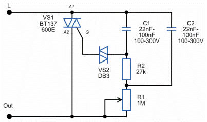
Rotary Dimmer Circuit

Rotary Dimmer Circuit

It looks like this real scheme of the dimmer. The parameters of the elements are indicated taking into account the scatter of different manufacturers, but the essence of this does not change. Triacs in a practical circuit can be set any, depending on the load power. Voltage - not lower than 400 V, since the instantaneous voltage in the network can reach 350 V.

From the size of the capacitors and resistors depends on the starting-end point of ignition, the stability of the lamp. With a minimum resistance of the rotary resistor R1 there will be minimal lamp burning.

With a strong desire, you can try to make a dimmer yourself. There are a large number of different schemes of homemade dimmers of different levels of complexity. You can learn more about homemade dimmer circuits in a series of articles by Boris Aladyshkin about homemade dimmers - How to make a dimmer yourself.


How to repair a dimmer

In conclusion - a few words about the repair of dimmers. Most often, the cause of the breakdown may be an excess of the maximum permissible load or a short circuit in the load. As a result, as a rule, the triac fails. The triac can be replaced by unscrewing the radiator and dropping the triac from the board. It is better to immediately put a powerful one at a higher current and voltage than a burned one. It also happens that the regulator fails, or the installation is broken.

The dimmer can be used as a voltage regulator, connecting any active load through it - an incandescent lamp, soldering iron, kettle, iron. But most importantly - the power of the dimmer (in other words, the maximum current of the triac) should correspond to the load.

See also at i.electricianexp.com:

  • Dimmers: device, varieties and connection methods
  • LED dimmers and their use
  • Types and designs of dimmers for lamps
  • How are dimmable LED lamps arranged and working, unlike ordinary ones?
  • Controlled sockets and switches ELRO

  •  
     
    Comments:

    # 1 wrote: | [quote]


    Wonderful thing is a dimmer. And the article is very useful.

    That's just for halogen lamps it is harmful as far as I know. Why? Because in halogen lamps, in contrast to conventional inertially filled lamps, the so-called iodine cycle occurs, which allows the filament to recover due to the return of tungsten atoms on it. The volume of the GL flask is very small. This process occurs at a certain temperature. In the case of ordinary LN, tungsten atoms settle on the bulb, reducing light transmission and a thinning filament. With a decrease in voltage, under-heating occurs and the iodine cycle does not work. Although if the voltage is reduced, then the spiral lasts longer.

     
    Comments:

    # 2 wrote: andy78 | [quote]


    I have connected through two dimmers five halogen lamps in the kitchen and a chandelier with six incandescent lamps. I have not yet noticed a strong influence of the dimmer on the life of halogen lamps. Incandescent lamps burn out more often.Even if it were the other way around, for me the convenience of having the ability to adjust the brightness of the light compensates for the possible reduction in the life of the halogen.

     
    Comments:

    # 3 wrote: | [quote]


    The potentiometer, by itself, does not change the phase angle. The capacitor changes it, but depending on the magnitude of the current passing through the regulating potentiometer! And at the minimum value of the potentiometer resistance, the current in the "capacitor - potentiometer" circuit will be maximum and the lamp will burn at full heat, and not vice versa, as the article says!

    And for andy78: LVs most often burn out, or rather spirals break, when turned on, especially in the cold season, or when installing a lamp in a suspended ceiling, behind which drafts or cooling air conditioner “walk”. Abrupt heating of a tungsten spiral at its ends with the middle not having time to heat up leads to its banal rupture due to uneven thermal expansion! And, the longer the spiral, the more likely it is to burn from a simple switch-on. A smooth inclusion (but not abrupt - snapped and immediately to full!) With the help of a dimmer gives the initial heating and preparation of the spiral for operation under full load without emergency consequences! The lowering transformer for halogen lamps of 12 V. gives the same effect. Success!

     
    Comments:

    # 4 wrote: | [quote]


    IN THE ARTICLE AUTOMATION OF PUMPS AND PUMP STATIONS, I WANT TO PAY ATTENTION TO THE DEVICE A2 FIGURE 5. WHAT THE INSTRUMENT TO INCLUDE IF

     
    Comments:

    # 5 wrote: andy78 | [quote]


    WHAT IS THE DEVICE FOR TURNING ON THE IF

    This is an electronic pump dry running relay. With it, the pump "understands" when it needs to shut off when there is no water in the suction pipe.

     
    Comments:

    # 6 wrote: | [quote]


    I want to add some points:

    If you decide to make a dimmer yourself, then consider the safety precautions as much as possible. For example, the legs of the triac are strongly recommended to be isolated by cambric. On this occasion, he personally observed when the load was turned on, the arc between the legs of the triac, after which the triac itself successfully failed. And yet, do not spare the solder, since good soldering is the key to reliability.

     
    Comments:

    # 7 wrote: | [quote]


    ............. and the maximum length of the wires is about 10 meters, and the circuit may be critical to interference and interference .............

    At the control input of the push-button dimmer, I put a T-shaped R filter, (the ratings depending on the length of the control wires are 0.1 .... 5 MΩ) ... and the interference disappears ...

    Tested on products of Italians - BTicino, a member of the Legrand group of companies.

     
    Comments:

    # 8 wrote: Frol_1 | [quote]


    Can the fan speed be dimmed? And then I bought, connected. But I did not see the effect. There is no smooth adjustment, when the controller rotates, it turns on sharply at revolutions closer to the maximum and at the same time some kind of bounce is heard in the fan. In the passport to the dimmer it is written that the load is from 40-600 watts, and the fan is only 15 watts. Maybe because of this?

     
    Comments:

    # 9 wrote: Sergei. | [quote]


    The principle of operation of the electric motor and the incandescent spiral is different. The dimmer cannot be adjusted, either a rheostat or a frequency converter is needed, but for a low-power fan the latter is bold))

     
    Comments:

    # 10 wrote: | [quote]


    Greetings. Help to deal with the problem. Two rooms have a dimmer. If in the first room the dimmer is turned on at full power, then in the second room, when the dimmer is turned off, the lamps turn off, and then they begin to burn faintly dimly. If the light is dimmed slightly in the first room, the problem disappears. The problem appeared today, a year and a half everything worked fine. Is there a problem in the dimmer or wiring? (in the room where the problem dimmer recently changed)

     
    Comments:

    # 11 wrote: | [quote]


    Jacob,
    A similar problem ... Who met and how to fight?

     
    Comments:

    # 12 wrote: a guest | [quote]


    Jacob, one moment - do you have a button illumination on the dimmer? if so, that’s normal. especially for energy-saving lamps. But nature is simple - a small current flows through the halogen on the dimmer. He is very small - because the glow is barely noticeable, perhaps just blinking.

     
    Comments:

    # 13 wrote: Vlad | [quote]


    I had a dimmer for 2 lamps of 60 watts in the bedroom. 5 years light bulbs have served. Good stuff.

     
    Comments:

    # 14 wrote: | [quote]


    A very useful article, and informative. Thanks to the author. However, a question arose, please clarify. Or I don’t understand the essence of the processes ... "With the minimum resistance of the rotary resistor R1 there will be minimal lamp burning." Those. the resistor R1 is shorted by the slider of the potentiometer, all the mains voltage is applied to the capacitor C2, the latter is charged very quickly, and while the dynistor and, accordingly, the trinistor remain locked? In my opinion, a dubious assumption. This happens if R1 has maximum resistance. In this case, the charge C2 occurs much more slowly, the breakdown voltage of the diak occurs later, therefore, the power supplied to the load, and, accordingly, the brightness of the lamp will be less, up to the shutdown. Everything is exactly the opposite. Accept and so on.

     
    Comments:

    # 15 wrote: | [quote]


    Dim. The essence of the processes can be 2 types. A break or constant flows through the wire. Email The circuit controls the power radio component. 1. The power part does not open completely (opening is regulated, like a water tap). 2. The part opens completely, but for a certain time in some kind of cycle, where the cycle is the frequency of the device. In this case, this is the 1st principle.

     
    Comments:

    # 16 wrote: a | [quote]


    About 100Hz explain where they came from? Was 50 cut off by the triac (did not straighten the bridge) and suddenly 100Hz?

     
    Comments:

    # 17 wrote: Michael | [quote]


    When dimming halogen lamps, it should be borne in mind that when the supply voltage is reduced to 90% of the nominal, the "halogen cycle" ceases to work, and the halogen turns into a conventional incandescent lamp with a corresponding deterioration in performance (moreover, under the influence of bombarding bromine, corrosion of colder areas begins spirals, leading, naturally, to a decrease in lifetime). And an increase in voltage above the nominal by only 6% reduces the service life by half. Because of these limitations, it is not recommended to adjust their brightness, and when there is still a need, you should not go beyond the range (by the way, very narrow) of the "harmless" values ​​of the supply voltage. In addition, the lamp operating in the dimming mode, it is necessary from time to time to turn on at full power to clean the walls of the bulb and regenerate the tungsten filament.

     
    Comments:

    # 18 wrote: | [quote]


    The ingenious scheme ... Is there anything that with a decrease in brightness the ripple coefficient and duty cycle will increase ?? That is, it will increase And the spread between the brightest and most dim state of the bulb, And the time between bursts of brightness.

    It’s necessary to think of adjusting the brightness of household lighting using a pulsed method! That is, it is not so much the instantaneous brightness that is regulated as the average, but the role of the "averager" is safely left to our eyes. Well, who does not mind your eyes, use such schemes.

    If, when designing LCD monitors, they strive to get rid of this PWM control by the brightness of the backlight, then it only comes to household lighting. Hm ...

    The pulsation coefficient of an incandescent lamp in its normal form is 15%, which fits into the standards. But! Just not when working with flickering screens (CRT, LCD with PWM, etc.), in the case of which even 15% is too much. And after the use of such a "device", the incandescent lamp will cease to fit into the norms in general under any conditions.

    Why is it stupid not to put the rheostat in series with the lamp? Some articles write that, say, such a scheme does not save energy.Well, well, apparently, they did not even study at school and do not know that the heat loss is P = U ^ 2 / R. The greater the resistance we introduce into the circuit, the lower the loss. So why be smart? Yes, and to the detriment of health.

    And if you are smart, then you need to make a rectifier and feed the incandescent lamp with direct current. Then there will be no ripples at all and at any brightness.

     
    Comments:

    # 19 wrote: Alexander | [quote]


    Please tell me, if the capacitance of the capacitors in the circuit is increased in times, that is, from 0.1 to 0.2 μF, will this greatly affect the operation of the circuit or not?

     
    Comments:

    # 20 wrote: igor | [quote]


    For 10 years of using the dimmer in a room with 15 halogens of 35 watts each, not a single one has burned out, a 600 watt dimmer has burned out. Change to 800.

     
    Comments:

    # 21 wrote: Alexei | [quote]


    Sergei,

    Quote: Sergey
    The potentiometer, by itself, does not change the phase angle. The capacitor changes it, but depending on the magnitude of the current passing through the regulating potentiometer! And at the minimum value of the potentiometer resistance, the current in the "capacitor - potentiometer" circuit will be maximum and the lamp will burn at full heat, and not vice versa, as the article says!

    The current through the potentiometer, if you like, determines only the charge time of the capacitor. And the phase angle does not change the capacitor, but the triac and voltage at which the DB3 dinistor opens. The encoder and potentiometer is just an RC circuit that sets the rate of voltage rise on the dynistor, and as a result, the opening of the triac.

    Quote: Frol_1
    Can the fan speed be dimmed? And then I bought, connected. But I did not see the effect.

    The fan has an induction motor, most likely. there may be a change in speed due to a decrease in the voltage on the winding, but the dimmer does not regulate it normally, and your observations regarding the minimum power (40-600W) are also correct, the dimmer may not work correctly with a small load.

    Boris,
    Now calculate how much heat will be released on the rheostat. The scheme is not ingenious, but you are wrong, it is used everywhere, and the role of the "averager" is assigned to how much our eyes have, and how much the thermal incerion of the spiral. As for PWM and LCD monitors, you are wrong, in general, with normal brightness control, I personally have not seen such. But monitors with LED backlight (although this is basically an LCD, but of course it is more visible to marketers) often flicker. This is especially noticeable in phones at low brightness. As when shooting the screen with the camera, and with the naked eye. If essentially, then the more powerful the lamp, the less noticeable the ripple. If you want, do an experiment, connect the cartridge through a diode and screw in a light bulb of 100 watts and less than 40 watts (if you find it, I personally used ancient indicator lamps from electrical panels, those with a long and thin coil and wrapped around it like a Christmas tree garland, I think you understand the look). So these lamps just flickered like in a disco, and 100 watts glowed relatively smoothly even through the diode (consider power ripple 50%.

    Quote: a
    When the dimmer is turned off, the lamps turn off, and then they begin to burn faintly dimly. If the light is dimmed slightly in the first room, the problem disappears. The problem appeared today, a year and a half everything worked fine. Is there a problem in the dimmer or wiring? (in the room where the problem dimmer recently changed)

    The dimmer in the "zero" position should click - i.e. there should be a switch to be like in the first photo in the article. And this can also happen if somewhere there is a leak on the dimmer board.

    Quote: a
    About 100Hz explain where they came from? Was 50 cut off by the triac (did not straighten the bridge) and suddenly 100Hz?

    At 50 Hz, two half-waves of alternating voltage. With each cut. How many times have they been circumcised? 100. And that 100 Hz.

     
    Comments:

    # 22 wrote: Eva veg | [quote]


    Schemes of this type should only be used to adjust the heating temperature of something, for example, a soldering iron tip. You can, of course, and for lighting, if you do not mind your health and those around you.Ripples of light are transmitted through the eyes to the brain and are detrimental to the whole organism. I recommend to listen.

    And yet, at least “cut”, at least do not “cut” at a network frequency of 50 Hz, the filament pulsates with a frequency of 100 Hz. Only without circumcision, due to the inertia of the thread, is the light softer, but also harmful (do not read in electric light, as the relatively old wisdom says). But, if you just straighten it, as suggested, the current will switch from alternating to pulsating, which will not change anything. We need a low-pass filter so that it becomes constant, and this will be 310 V. We do not have such bulbs.

    I apologize for the "inertia", you should read the "inertia". Such a naked circuit is a source of strong interference in the low-frequency range. And the triac must be protected by a snubber chain!