Categories: Featured Articles » Practical Electronics
Number of views: 106560
Comments on the article: 6
Homemade dimmers. Part one. Types of Thyristors
 The article describes the use of thyristors, provides simple and illustrative experiments to study the principles of their operation. Practical instructions for checking and selecting thyristors are also given.
Homemade dimmers
In articles "Dimmers: device, varieties and connection methods" and "Device and circuit dimmer" It was told about the use of industrial dimmers. But, despite the variety and availability of such devices on sale, sometimes still, you have to remember the forgotten old, and assemble the dimmer according to a fairly simple amateur scheme.
The power of the device that is on sale may not be enough, or there are simply parts so that they are not stupidly lost, so let there be at least something. Also dimmer it doesn’t have to regulate the light at all, you can adapt it, for example, to a soldering iron. In general, there are plenty of applications, a ready-made device can always come in handy.
Almost all such devices are made using thyristors, which should be discussed separately, well, at least briefly, so that the principle of operation thyristor regulators was clear and understandable.
Types of Thyristors
Title thyristor implies several varieties, or as they say, a family of semiconductor devices. Such devices are a structure of four p and n layers, forming three consecutive p-n (p-n letters are Latin: from positive and negative) transitions.
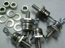
Fig. 1. Thyristors
If conclusions are drawn from the extreme regions p n, the resulting device is called a diode thyristor, in another way dinistor. It looks similar to a diode of the D226 or D7ZH series, only diodes have only one p-n junction. The design and layout of the KN102 dinistor is shown in Figure 2.
The scheme of its inclusion is also shown there. If we conclude from another pn junction, we get a triode thyristor, called a trinistor. Two trinistors can be located in one case at once, connected in the opposite direction - in parallel. This design is called triac and is designed to work in AC circuits, since it can pass both positive and negative half-periods of voltage.
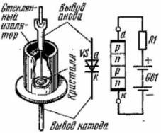
Figure 2. The internal device and the switching circuit of the diode thyristor KN102
The output of the cathode, region n, is connected to the housing, and the output of the anode through the glass insulator is connected to region p, as shown in Figure 1. It also shows the inclusion of a dynistor in the power circuit. The power supply must be connected in series with the dinistor.just as if it were ordinary diode. Figure 3 shows the volt - ampere characteristic of the dinistor.
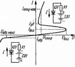
Figure 3. Volt - ampere characteristic of a dinistor
From this characteristic it is seen that the voltage to the dynistor can be applied both in the opposite direction (in the figure in the lower left quarter) and in the forward one, as shown in the upper right quarter of the figure. In the opposite direction, the characteristic is similar to that of a conventional diode: an insignificant reverse current flows through the device, practically we can assume that there is no current.
Of greater interest is the direct branch of the characteristic. If the voltage is applied to the dinistor in the forward direction and gradually increases, then the current through the dinistor will be small, and will vary slightly. But only until it reaches a certain value, called the switching voltage of the dinistor. In the figure, this is indicated as Uincl.
At this voltage, an avalanche-like increase in current occurs in the four-layer internal structure, the dynistor opens, passes into a conducting state, as evidenced by a section with negative resistance on the characteristic. The voltage of the cathode – anode section decreases sharply, and the current through the dinistor is limited only by the external load, in this case, the resistance of the resistor R1. The main thing is that the current should be limited at a level not higher than the maximum permissible, which is specified in the reference data.
The maximum permissible current or voltage is the value at which the normal operation of the device for a long time is guaranteed. Moreover, you should pay attention to the fact that only one of the parameters reaches the maximum permissible value: if the device operates in the maximum permissible current mode, then the operating voltage must be lower than the maximum permissible one. Otherwise, the normal operation of the semiconductor device is not guaranteed. Of course, you don’t need to specifically strive to achieve the maximum permissible parameters, but if that happened ...
This direct current will flow through the dinistor until the dinistor is turned off in some way. To do this, stop the passage of direct current. This can be done in three ways: open the power circuit, short-circuit the dynistor using a jumper (all current will pass through the jumper, and the current through the dynistor will be zero), or reverse the polarity of the supply voltage. This happens if you feed the dinistor and the load with alternating current. The tripping thyristor - trinistor has the same shutdown methods.
Dinistor marking
It consists of several letters and numbers, the most common and available are domestic devices of the KN102 series (A, B ... I). the first letter K, indicates that it is a silicon semiconductor device, N that it is a dynistor, the numbers 102 are the development number, but the last letter determines the voltage on.
The entire guide will not fit here, however, it should be noted that KN102A has a turn-on voltage of 20V, KN102B 28V, and KN102I has as many as 150V. When the devices are switched on sequentially, the switching voltage is added, for example, two KN102A will give a total voltage of 40V. Dinistors manufactured for the defense industry, instead of the first letter K, have the number 2. The same rule is used in the labeling of transistors.
Currently quite widespread symmetrical dinistors. To imagine this, it is enough to connect two ordinary dinistors in the opposite direction - in parallel. Such dinistors turn on when voltage of any polarity or alternating voltage is applied. Used in trigger driver circuitry in electronic transformers and energy-saving lamps, as well as a threshold element in thyristor regulators, which will be described later. One of these dinistors is marked DB3.
This logic of the operation of the dinistor allows you to collect enough on its basis simple pulse generators. A diagram of one of the options is shown in Figure 4.
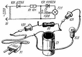
Figure 4. Dinistor generator
The principle of operation of such a generator is quite simple: the mains voltage rectified by the VD1 diode through the resistor R1 charges the capacitor C1, and as soon as the voltage across it reaches the switching voltage of the VS1 dynistor, the latter opens, and the capacitor discharges through the EL1 bulb, which gives a short flash, after which the process repeats first. In real circuits, instead of a bulb, a transformer can be installed, from the output winding of which pulses can be removed, used for any purpose, for example, as opening pulses.
Read on in the next article.
Continuation: Homemade dimmers. Part two. Thyristor device
Boris Aladyshkin
See also at bgv.electricianexp.com
:
