Categories: Featured Articles » Practical Electronics
Number of views: 205242
Comments on the article: 8
Thyristor Power Regulators
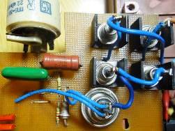 Thyristor power controllers are one of the most common amateur radio designs, and this is not surprising. After all, everyone who has ever used an ordinary 25 - 40 watt soldering iron, its ability to overheat is even very well known. The soldering iron begins to smoke and hiss, then, soon enough, the tinned sting burns out, turns black. Soldering with such a soldering iron is already completely impossible.
And here the power regulator comes to the rescue, with the help of which you can set the temperature for soldering quite accurately. It should be guided by the fact that when a soldering iron touches a piece of rosin, it smokes well, so, medium, without hissing and splashing, not very vigorously. You should focus on the fact that the soldering is contour, shiny.
Of course, modern soldering stations They are equipped with thermally stabilized soldering irons, digital displays and adjustable heating temperatures, but they are too expensive compared to a conventional soldering iron. Therefore, with insignificant volumes of soldering work, it is quite possible to do with a conventional soldering iron with a thyristor power regulator. At the same time, the quality of the soldering, which may not be right away, will turn out to be excellent, is achieved by practice.
Another area of application of thyristor regulators is brightness control. Such regulators are sold in electrical stores in the form of conventional wall switches with a rotary handle. But here the ambush lies in wait for the buyer: modern energy saving lamps (often referred to in the literature as compact fluorescent lamps (CFLs)) they simply do not want to work with such regulators.
The same unpredictable option will turn out in the case of regulating the brightness of LED lamps. Well, they are not intended for such work, and that’s it: the rectifier bridge with an electrolytic capacitor located inside the CFL will simply not let the thyristor work. Therefore, an adjustable "nightlight" with such a regulator can only be created using an incandescent lamp.
However, here you should remember about electronic transformersdesigned to power halogen lamps, and in amateur radio designs for a variety of purposes. In these transformers, after the rectifier bridge, for some reason, apparently in order to save, or simply to reduce the size, an electrolytic capacitor is not installed. It is this “saving” that allows you to adjust the brightness of the lamps using thyristor regulators.
If you strain your imagination, you can still find many more areas where the use of thyristor regulators is required. One of these areas is the regulation of revolutions of power tools: drills, grinders, screwdrivers, rotary hammers, etc. etc. Naturally, thyristor regulators are located inside instruments powered by AC power.Watch -Types and arrangement of revolutions of collector engine speed.
All such a regulator is built into the control button and is a small box inserted into the handle of the drill. The degree of pressing the button determines the frequency of rotation of the cartridge. In the event of failure, the entire box changes immediately: for all the apparent simplicity of the design, such a regulator is absolutely not suitable for repair.
In the case of tools running on direct current from batteries, power control is performed using transistors mosfet pulse width modulation method. The PWM frequency reaches several kilohertz, so through the body of the screwdriver you can hear a high frequency squeak. This squeak motor winding.
But in this article, only thyristor power controllers will be considered.Therefore, before considering the regulator circuit, you should remember how it works thyristor.
In order not to complicate the story, we will not consider the thyristor in the form of its four-layer p-n-p-n structure, draw a current-voltage characteristic, but simply describe in words how it works, the thyristor. To begin with, in a direct current circuit, although thyristors are almost not used in these circuits. After all, turning off the thyristor working on direct current is quite difficult. It’s the same as stopping the horse.
Nevertheless, high currents and high voltages of thyristors attract developers of various, as a rule, quite powerful DC equipment. To turn off the thyristors, you have to go to various complications of the circuits, tricks, but in general the results are positive.
The thyristor designation on the circuit diagrams is shown in Figure 1.
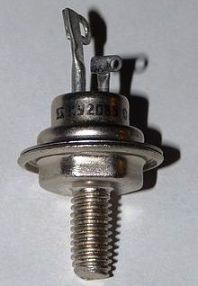
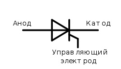
Figure 1. Thyristor
It is easy to see that in its designation on the circuits, the thyristor is very similar to ordinary diode. If you look, then it, the thyristor, also has one-sided conductivity, and therefore, can rectify alternating current. But he will only do this if a positive voltage is applied to the control electrode relative to the cathode, as shown in Figure 2. According to old terminology, the thyristor was sometimes called a controlled diode. As long as the control pulse is not applied, the thyristor is closed in any direction.
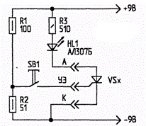
Figure 2
How to turn on the LED
Everything is very simple here. To the DC voltage source 9V (you can use the battery "Krona") through the thyristor Vsx connected LED HL1 with a limiting resistor R3. Using the SB1 button, the voltage from the divider R1, R2 can be applied to the control electrode of the thyristor, and then the thyristor will open, the LED starts to glow.
If now release the button, stop holding it pressed, then the LED should continue to light. Such a short press on the button can be called impulse. Repeated and even repeated pressing of this button will not change anything: the LED will not go out, but it will not shine brighter or dimmer.
Pressed - released, and the thyristor remained open. Moreover, this condition is stable: the thyristor will be open until external influences remove it from this state. This behavior of the circuit indicates the good condition of the thyristor, its suitability for work in a device under development or repair.
Little remark
But exceptions to this rule often occur: the button is pressed, the LED lights up, and when the button is released, it went out, as if nothing had happened. And what's the catch, what did you do wrong? Maybe the button was pressed not long enough or not very fanatically? No, everything was done fairly conscientiously. It’s just that the current through the LED turned out to be less than the holding current of the thyristor.
In order for the described experiment to be successful, you just need to replace the LED with an incandescent lamp, then the current will become more, or choose a thyristor with a lower holding current. This parameter for thyristors has a significant scatter, sometimes it is even necessary to select a thyristor for a specific circuit. Moreover, one brand, with one letter and from one box. Imported thyristors, which have recently been preferred, are somewhat better with this current: it’s easier to buy, and the parameters are better.
How to close a thyristor
No signals applied to the control electrode can close the thyristor and turn off the LED: the control electrode can only turn on the thyristor. There are, of course, lockable thyristors, but their purpose is somewhat different than banal power controllers or simple switches. A conventional thyristor can be turned off only by interrupting the current through the anode - cathode section.
This can be done in at least three ways. First, stupidly disconnect the entire circuit from the battery. Recall Figure 2. Naturally, the LED will turn off.But when reconnected, it will not turn on by itself, since the thyristor has remained closed. This condition is also sustainable. And to bring him out of this state, to light the light, only pressing the SB1 button will help.
The second way to interrupt the current through the thyristor is simply to take and short the terminals of the cathode and anode with a wire jumper. In this case, the entire load current, in our case it is only an LED, will flow through the jumper, and the current through the thyristor will be zero. After the jumper is removed, the thyristor will close and the LED will turn off. In experiments with similar schemes, tweezers are most often used as a jumper.
Suppose that instead of an LED in this circuit there will be a sufficiently powerful heating coil with high thermal inertia. Then it turns out almost ready power regulator. If the thyristor is switched in such a way that the spiral is turned on for 5 seconds and turned off for the same amount of time, then 50 percent power is allocated in the spiral. If, during this ten-second cycle, switching on takes only 1 second, then it is obvious that the spiral will release only 10% of the heat from its power.
With approximately such time cycles, measured in seconds, the microwave power control works. Simply using a relay, the RF radiation is turned on and off. Thyristor controllers operate at the frequency of the mains, where time is measured in milliseconds.
The third way to turn off the thyristor
It consists in reducing the load voltage to zero, or even reversing the polarity of the supply voltage. This is precisely the situation obtained when the thyristor circuits are supplied with an alternating sinusoidal current.
When the sinusoid passes through zero, it changes its sign to the opposite, so the current through the thyristor becomes less than the holding current, and then completely equal to zero. Thus, the problem of turning off the thyristor is solved as if by itself.
Thyristor power controllers. Phase regulation
So, the matter is left to the small. To get phase control, you just need to apply a control pulse at a certain time. In other words, the pulse must have a certain phase: the closer it is to the end of the half-cycle of the alternating voltage, the smaller the amplitude of the voltage will be on the load. The phase control method is shown in Figure 3.
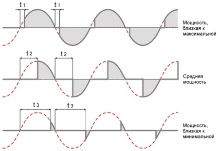
Figure 3. Phase regulation
In the upper fragment of the picture, the control pulse is applied almost at the very beginning of the half-wave of the sinusoid, the phase of the control signal is close to zero. In the figure, this time is t1, therefore, the thyristor opens almost at the beginning of the half-cycle, and a power close to maximum is allocated in the load (if there were no thyristors in the circuit, the power would be maximum).
The control signals themselves are not shown in this figure. Ideally, they are short pulses, positive with respect to the cathode, applied in a certain phase to the control electrode. In the simplest schemes, this can be a linearly increasing voltage obtained by charging a capacitor. This will be discussed below.
On the average graph, the control pulse is applied in the middle of the half-cycle, which corresponds to the phase angle Π / 2 or time t2, so only half of the maximum power is allocated in the load.
In the lower graph, the opening pulses are applied very close to the end of the half-cycle, the thyristor opens almost before it has to close, according to the graph this time is indicated as t3, so the power in the load is allocated insignificant.
Thyristor switching circuits
After a brief review of the principle of operation of thyristors, you can probably bring several power regulator circuits. Nothing is invented here; everything can be found on the Internet or in old radio magazines. The article simply provides a brief overview and job description thyristor regulator circuits. When describing the operation of the circuits, attention will be paid to how thyristors are used, what thyristor switching circuits exist.
As was said at the very beginning of the article, the thyristor rectifies an alternating voltage like a regular diode. It turns out half-wave rectification. Once upon a time, through a diode, incandescent lamps on stairwells turned on: there was a little light, it dazzled in my eyes, but then the lamps burn out very rarely. The same thing happens if the dimmer is performed on one thyristor, only the possibility of regulating an already insignificant brightness appears.
Therefore, power controllers control both half-cycles of the mains voltage. For this, counter-parallel connection of thyristors is applied, triacs or the inclusion of a thyristor in the diagonal of the rectifier bridge.
For clarity of this statement, we will further consider several circuits of thyristor power controllers. Sometimes they are called voltage regulators, and which name is more correct, it is difficult to solve, because along with voltage regulation, power is also regulated.
The simplest thyristor regulator
It is designed to regulate the power of the soldering iron. Its circuit is shown in Figure 4.
Figure 4. Scheme of the simplest thyristor power controller
To regulate the power of the soldering iron, starting from zero, there is no point. Therefore, we can restrict ourselves to regulating only one half-cycle of the mains voltage, in this case, positive. The negative half-cycle passes without changes through the VD1 diode directly to the soldering iron, which ensures its half power.
The positive half-cycle passes through the thyristor VS1, allowing regulation. The thyristor control circuit is extremely simple. These are resistors R1, R2 and capacitor C1. The capacitor is charged through the circuit: the upper wire of the circuit, R1, R2 and the capacitor C1, load, the lower wire of the circuit.
A thyristor control electrode is connected to the positive terminal of the capacitor. When the voltage across the capacitor rises to the turn-on voltage of the thyristor, the latter opens, passing into the load a positive half-cycle of the voltage, or rather part of it. The capacitor C1 naturally discharges, thereby preparing for the next cycle.
The charge speed of the capacitor is regulated using a variable resistor R1. The faster the capacitor is charged to the thyristor opening voltage, the earlier the thyristor opens, the greater part of the positive half-cycle of the voltage will enter the load.
The circuit is simple, reliable, it is quite suitable for a soldering iron, although it regulates only one half-period of the mains voltage. A very similar diagram is shown in Figure 5.
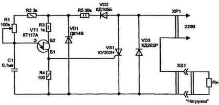
Figure 5. Thyristor power controller
It is somewhat more complicated than the previous one, but it allows you to adjust more smoothly and accurately, due to the fact that the control pulse generation circuit is assembled on a KT117 double-base transistor. This transistor is designed to create pulse generators. More, it seems, is not capable of anything else. A similar circuit is used in many power controllers, as well as in switching power supplies as a driver for a triggering pulse.
As soon as the voltage across capacitor C1 reaches the threshold of the transistor, the latter opens and a positive pulse appears on pin B1, opening the thyristor VS1. Resistor R1 can adjust the charge rate of the capacitor.
The faster the capacitor is charged, the earlier the opening pulse appears, the greater the voltage will enter the load. The second half-wave of the mains voltage passes into the load through the VD3 diode without changes. A rectifier VD2, R5, a Zener diode VD1 is used to power the control pulse shaper circuit.
Here you can ask, and when the transistor opens, what is the threshold? The opening of the transistor occurs at a time when the voltage at its emitter E exceeds the voltage at the base of B1. Bases B1 and B2 are not equivalent, if they are interchanged, the generator will not work.
Figure 6 shows a circuit that allows you to adjust both half-cycles of voltage.
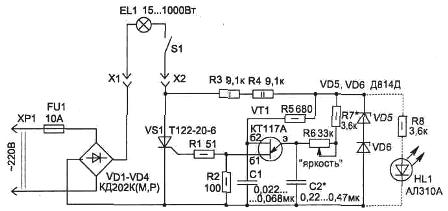
Figure 6
The diagram is a dimmer. The mains voltage is rectified by the bridge VD1-VD4, after which the ripple voltage is supplied to the lamp EL1, thyristor VS1, and through the resistors R3, R4 to the zener diodes VD5, VD6, from which the control circuit is powered. The use of a rectifier bridge in the circuit allows the regulation of positive and negative half-cycles using only one thyristor.
The control circuit is also performed on a two-base transistor KT117A. The charge speed of the timing capacitor C2 is changed by the resistor R6, which causes the phase of the thyristor control signal to change.
A small remark can be made about this circuit: the current in the load consists only of the positive half-cycles of the network obtained after the bridge rectifier. If it is required to obtain the positive and negative parts of the sinusoid in the load, it is enough, without changing anything in the circuit, to turn on the load immediately after the fuse. In place of the load, simply install a jumper. Such a circuit is shown in Figure 7.
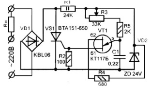
Figure 7. Scheme of thyristor power controller
The KT117 transistor is an invention of the Soviet electronic industry and has no foreign analogues, but if necessary it can be assembled from two transistors according to the circuit shown in Figure 8. Suddenly someone will undertake to assemble a similar circuit, where can I get such a transistor?
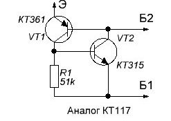
Figure 8
In the circuits shown in figures 6 and 7, the thyristor is used in combination with a diode bridge. This inclusion makes it possible with the help of one thyristor to control both half-periods of alternating voltage. But at the same time, 4 additional diodes appear, which generally increases the dimensions of the structure.
Continuation of the article: Thyristor power controllers. Circuits with two thyristors
Boris Aladyshkin
See also at i.electricianexp.com
:

