Categories: Featured Articles » Practical Electronics
Number of views: 128967
Comments on the article: 3
Thyristor power controllers. Circuits with two thyristors
Begin the article here: Thyristor Power Regulators
 Somewhat better results are obtained using circuits using two thyristors connected in opposite directions - in parallel: there is no need for extra diodes, and thyristors are easier to operate. Such a circuit is shown in Figure 1.
The control pulses for each thyristor are generated separately by the circuit on the dynistors V3, V4 and capacitors C1, C2. The power in the load is regulated by a variable resistor R5.
But two thyristors are also impermissible luxury. Therefore, the electronic industry has mastered the production of triacs, or, as they are otherwise called symmetrical thyristors.
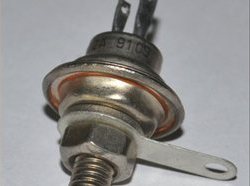
Dimensions and body shape triac similar to a conventional thyristor, only two thyristors “live” inside it, connected in the same way as thyristors V1 and V2 are connected in Figure 1. In this case, the triac has only one control electrode, which simplifies the control circuit. In general, like Siamese twins.
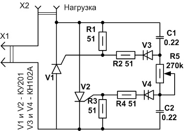
Figure 1. Scheme of a thyristor power controller with two thyristors
A very simple control circuit is obtained using a normal neon bulb as a threshold element. Radio amateurs are thrifty people, akin to Gogol's Plyushkin, and store a lot of all kinds of trash in their stocks. But it’s known that trash is such a thing that it was thrown away yesterday, and tomorrow it is already needed. Therefore, to find in the trash a neon bulb that remains from the repair of an electric kettle is not particularly difficult.
Historical reference
On neon bulbs, sound frequency generators were once made. More precisely, sound probes. The oscillation shape of such generators is sawtooth. Using several neon lamps, multivibrator circuits were built, in addition, neon lamps were an integral part of amplitude selectors. On neonka, it’s easiest to collect all kinds of emergency lights, with a period of even a few seconds. It is enough to choose the resistor and capacitor of the corresponding ratings.
The circuit of the power regulator on a triac with a neon bulb is shown in Figure 2.
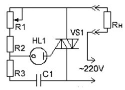
Figure 2Scheme of the power controller on the triac
The capacitor C1 is charged from the network through the load Rн and resistors R1 ... R3. When the voltage across the capacitor reaches the ignition voltage of the neon lamp HL1, the lamp ignites, and the capacitor C1 discharges through the circuit R3, HL1, the control electrode is the cathode of the triac VS1, which leads to the opening of the triac. Resistor R1, you can change the charge speed of the capacitor C1, and therefore the phase of the opening of the triac.
But a neon lamp in modern times is pure exotic. The same can be said about KT117 transistors and KN102 dinistors. Modern electronic industry offers bipolar for such purposes dinistor DB3.
The logic of the dinistor is extremely simple: when connected to an electric circuit, the dinistor is closed. When the voltage increases to a certain value (opening voltage), the dinistor opens and conducts current. Well, exactly like a neon lamp. In this case, it is necessary to apply voltage in a certain polarity, like a diode.
Inside DB3, two dinistors are hidden, turned on in opposite directions, which allows it to be used in alternating current circuits. And do not monitor polarity; DB3 will determine what it needs to do. DB3 operates at a voltage of about 32 ... 33V, while the direct current can reach 2A. The main purpose of this modest radio element is the trigger circuit power suppliesas well as energy-saving lamps or in another way CFL. It is from the boards of faulty CFLs that can not always be repaired, and DB3 dinistors are extracted.
Very few details will be required to create a controller based on the DB3 dinistor.The controller circuit is shown in Figure 3.
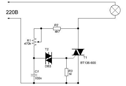
Figure 3. Schematic of a dinistor based regulator
The circuit is very similar to the circuit with a neon lamp, so it does not need special explanations. As soon as the voltage across capacitor C1 reaches the operating voltage of the dynistor T2, the latter opens and the capacitor discharges to the control electrode of the triac T1, the triac opens and passes the current to the load. The phase of the control pulse depends on the charge speed of the capacitor C1, which is regulated by a variable resistor R1.
But electronic equipment does not stand still, not only TVs and computers are being improved. Phase power controllers are now available as integrated circuits. Quite popular in the environment of radio amateurs, a chip of a phase power regulator KR1182PM1, the typical circuit of which is shown in Figure 4.
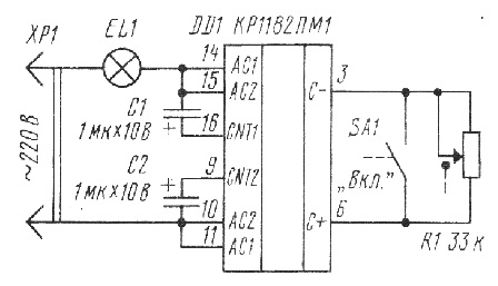
Figure 4. Typical wiring diagrammicrochips of a phase power regulator KR1182PM1
The chip is made in a plastic case DIP-16. Just a few details turn it into a phase power controller. Maximum adjustable power should not exceed 150W. In this case, you do not even need to install the chip on the radiator. Parallel connection of microcircuits is allowed - just stupidly one case is placed on top of another, and each output of the upper microcircuit is soldered to the same output of the lower one. There are exactly as many external parts as shown in the diagram.
To control the operation of the microcircuit, conclusions 3 and 6 are used. A variable resistor R1, which regulates power, is connected to them. Contact SA1 is also connected to this, and when closed, the load is disconnected.
Near pins 3 and 6, you can notice the marking C- and C +. It is in this polarity that one can connect electrolytic capacitor a sufficiently large capacitance (approximately 200 ... 500 μF), which, when the contact SA1 opens, will ensure a smooth switching on of the load, to the level that was set by the variable resistor R1. Such a control algorithm is very useful for incandescent lamps.
To increase the power of the regulated load, a triac is additionally connected to the microcircuit, which is provided for by the technical documentation. Then you can control a load of up to several kilowatts. See an example of such a scheme here: Homemade soft starter motor.
Of course, there are other types of power controllers that work according to different algorithms. Schemes are increasingly common controlled by microcontrollers. But in one article it’s impossible to talk about everything.
Boris Aladyshkin
See also at bgv.electricianexp.com
:
