Categories: Featured Articles » Practical Electronics
Number of views: 71716
Comments on the article: 5
Homemade dimmers. Part three. How to control a thyristor?
 How to turn on the thyristor? Turn on the thyristor with direct current.
The beginning of a series of articles about homemade dimmers:
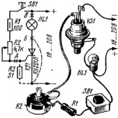
To answer this question you will have to assemble a simple schematic shown in the figure. 1. After the circuit is assembled, it should be connected to a constant voltage source. Best of all, if it is a regulated laboratory source with protection, at least from a short circuit, after all, what can happen during the experiments?
The variable resistor R2 motor should be set to the lower position in the diagram. Then, while holding down the SB1 button, (the light should not still be on), slowly move the slider upwards in the diagram. In some position of the engine, the lamp will light up, after which the button should be released, thereby removing the signal from the UE. After releasing the button, the light should remain on. How can all this be explained?
By rotating the resistor R2 engine, we increased the UE current, at a certain value of which, the characteristic of the thyristor was straightened and it opened, as was shown on figure 2 (see volt - ampere characteristic of the thyristor in the article "Thyristor device"). The resistor R1 is designed to limit the current through the RE so that it does not exceed the allowable level specified in the reference data. If you now release the SB1 button, the bulb will remain lit, since its current is quite enough to keep the thyristor in the open state. This point is also shown in the figure. 2like Iud.

Picture 1. Scheme for the experience of turning on the thyristor
If in this experiment to point A in the figure 1 If you turn on the milliammeter, then you can measure the current of the control electrode. If you test several instances of thyristors even of the same brand, the current of the control electrode at which the light comes on will be different, with a fairly significant spread. These currents can vary in the range of 10 - 15mA.
Also, using this circuit, you can determine the holding current of the thyristor, for which a milliammeter is connected to point B, and a variable resistor of 2.2 - 3.3K ohms, previously brought to zero, is connected to point B. After the thyristor can be turned on by turning the resistor R2, when the button SB1 is released, reduce the current in the load with the help of an additional variable resistor.
The smallest current at which the thyristor trips will be the holding current for this instance. The holding current, as well as the current of the control electrode, is small, of the order of 10 - 15 mA, but, in both cases, the smaller the better.
Thyristor control by pulse current
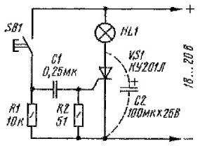
To conduct this experiment, the scheme shown in Figure 1 should be slightly modified, bringing it to a view in accordance with Figure 2.

Figure 2. Thyristor control by pulsed current
When the SB1 button is pressed, the capacitor C1 is charged through the UE of the thyristor, as a result of which the thyristor opens with a short pulse of the charging current, as evidenced by a luminous bulb. Releasing and then pressing the button will not lead to any changes, the light will remain on. It can be repaid only in the ways that were considered earlier, and in addition to them, by briefly connecting the capacitor C2, as shown by the dotted line. This capacitor shunts the thyristor, the current through it becomes equal to zero, as a result, the thyristor turns off. But only after that you can again use the SB1 button. To be ready for the next press, capacitor C1 discharges through resistor R1.
Thyristor in the device of the phase power regulator
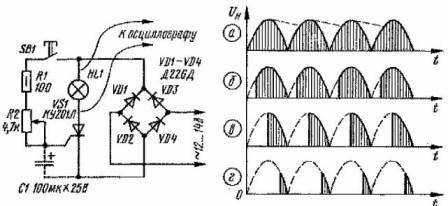
Figure 3 shows a diagram of the simplest power regulator on a trinistor, in the same time diagram of the output voltages.

Figure 3. Scheme for studying the power regulator
Depending on the magnitude of the control current, the thyristor has the property of opening at different voltages at the anode. This property is used in power regulator circuits. The diagram shows the points for connecting the oscilloscope, which will allow you to see firsthand the diagrams shown in the figure. If this is not possible, then you just have to take a word.
The regulator is powered by a transformer, as in previous experiments through diode bridge VD1 - VD4. It is impossible to install a filtering capacitor parallel to the bridge, since the voltage will take the form shown by a dotted line in Figure 3a, and the thyristor will not be able to turn off when the voltage passes through zero: the lamp, turning on once, will continue to burn.
First, the variable resistor R2 engine should be set to the upper position in the diagram and press the SB1 button. The resistance in the UE circuit in this case is small, only 100 Ω, and the current sufficient to open the thyristor will turn out at a voltage of a little more than one volt at the anode, at the very beginning of the half-cycle. Therefore, the bulb should be lit in full heat, which corresponds to the time diagram a, which can be observed on an oscilloscope.
This voltage is obtained as a result of the half-wave rectification of the sinusoid. Of course, there will be no vertical hatching inside half-periods, this is only in the figure. When you release the button, the light should go out when the rectified voltage passes through zero.
If you press the button again and slowly slide the variable resistor slider down in the diagram, then the brightness of the lamp will decrease, and on the oscilloscope you can see distorted pieces of a half-sinusoid. In the diagrams they are shown by vertical hatching. The power in the load will correspond to the shaded area - at this time the thyristor is open.
This is because, when the resistor R2 engine is moved down, the resistance in the control electrode circuit increases, and the RE current sufficient to open the thyristor is obtained with increasing values of the voltage at the anode.
This state of affairs is possible only up to diagram 3c, until the voltage at the anode reaches its maximum value. The shaded part of the diagram corresponds to 50% of the load power with a control range of only 50 - 100%. How to continue further regulation?
To do this, you should change the phase of the voltage on the UE relative to the phase of the voltage at the anode, which can be achieved in a very simple way. It is enough to connect the capacitor C1, as shown in the diagram with a dotted line. Now the thyristor will open at low values of the anode voltage, starting from the second part of the half-cycle, as shown in diagram 3d, which will expand the control range from 0 - 100%.
After studying the theory and conducting simple practical exercises, you can proceed to the manufacture of dimmers and power regulators.
Read on in the next article.
Continuation of the article: Homemade dimmers. Thyristor Practical Devices
Boris Aladyshkin, bgv.electricianexp.com
See also at bgv.electricianexp.com
:
