Categories: Featured Articles » Practical Electronics
Number of views: 60798
Comments on the article: 2
Methods and circuits for controlling a thyristor or triac
Thyristors are widely used in semiconductor devices and converters. Various power sources, frequency converters, regulators, excitation devices for synchronous motors and many other devices were built on thyristors, and recently they are replaced by transistor converters. The main task for the thyristor is to turn on the load at the time the control signal is applied. In this article we will look at how to control thyristors and triacs.
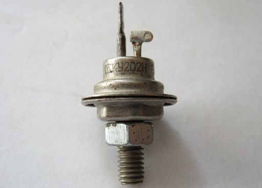
Definition
Thyristor (trinistor) is a semiconductor semi-controlled key. Semi-controlled - it means that you can only turn on the thyristor, it turns off only when the current in the circuit is interrupted or if a reverse voltage is applied to it.

He, like a diode, conducts current in only one direction. That is, for inclusion in the AC circuit to control two half-waves, two thyristors are needed, each one, although not always. The thyristor consists of 4 areas of the semiconductor (p-n-p-n).
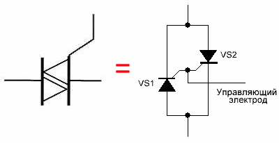
Another similar device is called triac - bidirectional thyristor. Its main difference is that it can conduct current in both directions. In fact, it represents two thyristors connected in parallel towards each other.
Main characteristics
Like any other electronic component, thyristors have a number of characteristics:
-
Voltage drop at maximum anode current (VT or UОС).
-
Forward closed voltage (VD (RM) or Ucc).
-
Reverse voltage (VR (PM) or Urev).
-
Forward current (IT or Ipr) is the maximum current in the open state.
-
Maximum Permissible Forward Current (ITSM) is the maximum peak current in open state.
-
Reverse current (IR) - current at a certain reverse voltage.
-
Direct current in a closed state at a certain forward voltage (ID or ISc).
-
Constant trigger control voltage (VGT or UU).
-
Control Current (IGT).
-
Maximum current control electrode IGM.
-
Maximum allowable power dissipation at the control electrode (PG or Pу)
Principle of operation
When voltage is applied to the thyristor, it does not conduct current. There are two ways to turn it on - apply voltage between the anode and cathode enough to open, then its operation will not differ from the dinistor.
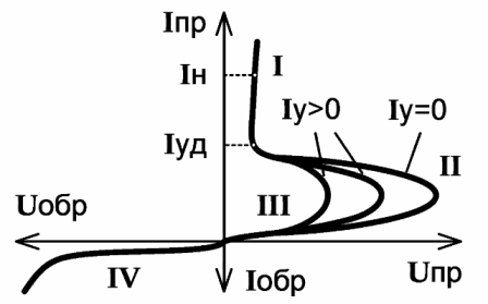
Another way is to apply a short-term pulse to the control electrode. The thyristor opening current is in the range of 70-160 mA, although in practice this value, as well as the voltage that needs to be applied to the thyristor, depends on the particular model and instance of the semiconductor device and even on the conditions in which it operates, such as, for example, ambient temperature Wednesday.
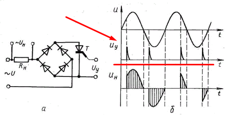
In addition to the control current, there is such a parameter as the holding current - this is the minimum anode current to keep the thyristor in the open state.
After opening the thyristor, the control signal can be turned off, the thyristor will be open as long as direct current flows through it and voltage is applied. That is, in a variable circuit, the thyristor will be open during that half-wave, the voltage of which biases the thyristor in the forward direction. When the voltage rushes to zero, the current will decrease. When the current in the circuit drops below the holding current of the thyristor, it will close (turn off).
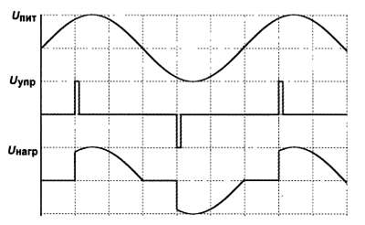
The polarity of the control voltage must coincide with the polarity of the voltage between the anode and cathode, as you can see in the oscillograms above.
The control of the triac is similar, although it has some features. To control a triac in an AC circuit, two pulses of control voltage are needed - for each half wave of a sine wave, respectively.
After applying a control pulse in the first half-wave (conditionally positive) of a sinusoidal voltage, the current through the triac will flow until the beginning of the second half-wave, after which it will close, like a conventional thyristor. After this, you need to apply another control impulse to open the triac on the negative half-wave. This is clearly illustrated in the following waveforms.
The polarity of the control voltage must correspond to the polarity of the applied voltage between the anode and cathode. Because of this, problems arise when controlling triacs using digital logic circuits or from the outputs of a microcontroller. But this is easily solved by installing a triac driver, which we will talk about later.
Common thyristor or triac control circuits
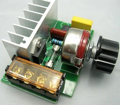
The most common circuit is a triac or thyristor regulator.

Here, the thyristor opens after there is a sufficient amount on the capacitor to open it. The opening moment is adjusted using a potentiometer or a variable resistor. The greater its resistance, the slower the capacitor charges. Resistor R2 limits the current through the control electrode.
This scheme regulates both half-periods, that is, you get full power control from almost 0% to almost 100%. This was achieved by setting the regulator in the diode bridgeThus, one of the half-waves is regulated.
A simplified circuit is shown below, only half of the period is regulated here, the second half-wave passes without change through the diode VD1. The principle of operation is similar.

Triac controller without a diode bridge allows you to control two half-waves.
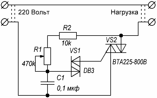
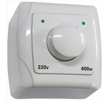
According to the principle of operation, it is almost similar to the previous ones, but both half-waves are already regulated with the help of the triac. The differences are that here the control pulse is supplied using a bi-directional DB3 dinistor, after the capacitor is charged to the desired voltage, usually 28-36 Volts. The charging speed is also regulated by a variable resistor or potentiometer. This scheme is implemented in most household dimmers.
Interesting:
Such voltage control circuits are called SIFU - a pulse phase control system.
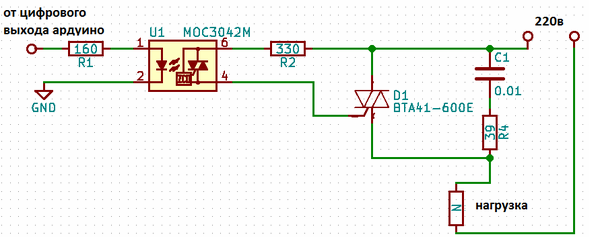
The figure above shows the option of controlling a triac using a microcontroller, using an example popular Arduino platform. The triac driver consists of an optosimistor and an LED. Since an optosymistor is installed in the driver output circuit, a voltage of the required polarity is always applied to the control electrode, but there are some nuances here.
The fact is that to adjust the voltage with the help of a triac or thyristor, it is necessary to apply a control signal at a certain point in time, so that the phase cut occurs to the desired value. If you randomly shoot control pulses, the circuit will certainly work, but adjustments will not work, so you need to determine when the half-wave passes through zero.
Since for us the polarity of the half-wave does not matter at the moment, it’s enough to simply track the moment of transition through zero. Such a node in the circuit is called a zero detector or a zero detector, and in English sources it is called “zero crossing detector circuit” or ZCD. A variant of such a circuit with a zero crossing detector on a transistor optocoupler is as follows:
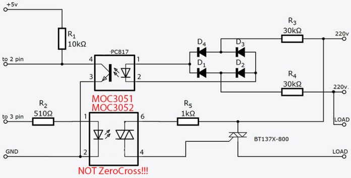
There are many optical drivers for controlling triacs, typical ones are the MOC304x, MOC305x, MOC306X line, manufactured by Motorola and others. Moreover, these drivers provide galvanic isolation, which will protect your microcontroller in the event of a breakdown of the semiconductor key, which is quite possible and likely. It will also increase the safety of working with control circuits by completely dividing the circuit into “power” and “operational”.
Conclusion
We told basic information about thyristors and triacs, as well as their management in circuits with a "change".It is worth noting that we did not address the topic of lockable thyristors, if you are interested in this issue - write comments and we will consider them in more detail. Also, the nuances of using and controlling thyristors in power inductive circuits were not considered. To control the “constant” it is better to use transistors, because in this case you decide when the key will open, and when it will close, obeying the control signal ...
See also at i.electricianexp.com
:
