Categories: Microcontroller circuits
Number of views: 29356
Comments on the article: 1
How to safely manage a 220 volt load using Arduino
For the Smart Home system, the main task is to control household appliances from a control device, be it an Arduino type microcontroller, a Raspberry PI type microcomputer or any other. But to do this directly does not work, let's figure out how to manage the 220 V load with Arduino.

To control AC circuits, the microcontroller is not enough for two reasons:
1. At the exit microcontroller a constant voltage signal is generated.
2. The current through the pin of the microcontroller is usually limited to 20-40 mA.
We have two options for switching using a relay or using a triac. The triac can be replaced by two thyristors turned on in parallel (this is the internal structure of the triac). Let's take a closer look at this.
220 load control IN using a triac and microcontroller
The internal structure of the triac is shown in the picture below.

The thyristor works as follows: when a forward bias voltage is applied to the thyristor (plus to the anode, and minus to the cathode), no current will pass through it until you apply a control pulse to the control electrode.
I wrote an impulse for a reason. Unlike a transistor, a thyristor is a SEMI-CONTROLLED semiconductor switch. This means that when the control signal is removed, the current through the thyristor will continue to flow, i.e. he will remain open. To close it, you need to interrupt the current in the circuit or change the polarity of the applied voltage.
This means that when holding a positive pulse on the control electrode, you need a thyristor in the AC circuit to pass only the positive half-wave. The triac can pass current in both directions, but because It consists of two thyristors connected towards each other.
The control pulses in polarity for each of the internal thyristors must correspond to the polarity of the corresponding half-wave, only if this condition is met, an alternating current will flow through the triac. In practice, such a scheme is implemented in common triac power controller.

As I already said, the microcontroller generates a signal of only one polarity, in order to coordinate the signal you need to use a driver built on an optosymistor.

Thus, the signal turns on the internal LED of the optocoupler, it opens the triac, which supplies the control signal to the power triac T1. As an optical driver, MOC3063 and the like can be used, for example, the photo below shows MOC3041.

Zero crossing circuit - zero phase crossing detector circuit. It is necessary for the implementation of various kinds of triac regulators on a microcontroller.
If the circuit is also without an optical driver, where the coordination is organized through a diode bridge, but in it, unlike the previous version, there is no galvanic isolation. This means that at the first voltage surge, the bridge can break through and high voltage will be at the output of the microcontroller, which is bad.

When you turn on / off a powerful load, especially an inductive nature, such as motors and electromagnets, voltage surges occur, so you need to install a snubber RC circuit in parallel with all semiconductor devices.

Relay and Arduino
To control relays with ARduino need to use an additional transistor to amplify the current.
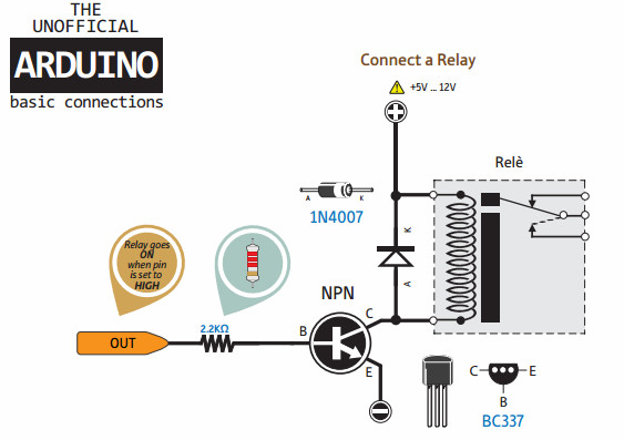
Please note that a bipolar transistor of reverse conductivity (NPN-structure) is used, it can be a domestic KT315 (beloved and well-known to everyone). The diode is needed to suppress surges of the EMF of self-induction in the inductance, this is necessary so that the transistor does not fail from a high applied voltage.Why this happens will explain the law of switching: "The current in the inductance cannot change instantly."
And when the transistor is closed (removal of the control pulse), the magnetic field energy accumulated in the relay coil needs to go somewhere, which is why the reverse diode is installed. Once again, I note that the diode is connected in the BACK direction, i.e. cathode to positive, anode to negative.
You can assemble such a scheme yourself, which is much cheaper, plus you can use relayrated for any constant voltage.
Or buy a ready-made module or a whole shield with a relay for Arduino:

The photo shows a homemade shield, by the way, it used KT315G to amplify the current, and below you see the same factory-made shield:

These are 4-channel shields, i.e. you can include as many as four lines of 220 V. In detail about shields and relays, we already posted an article on the site - Useful Shields for Arduino
The connection diagram of the load at a voltage of 220 V to Arduino through a relay:

Conclusion
Safe AC load management means first and foremost microcontroller security all the information described above is valid for any microcontroller, not just the board Arduino.
The main task is to provide the necessary voltage and current for controlling the triac or relay and galvanic isolation of the control circuits and the AC power circuit.
In addition to security for the microcontroller, this way you insure yourself so that you do not get an electric shock during maintenance. When working with high voltage, you must follow all safety rules, comply with PUE and PTEEP.
These schemes can be used and for controlling powerful starters and contactors. Triacs and relays in this case act as an intermediate amplifier and signal coordinator. On powerful switching devices, large coil control currents also depend directly on the power of the contactor or starter.
See also at i.electricianexp.com
: