Categories: Sharing experience, Novice electricians
Number of views: 16895
Comments on the article: 2
Features of modern magnetic starters and their application
It is necessary to consider this topic from magnetic starters from representatives of the Soviet era. Bright representatives are PML and the like. Starters are used to switch a powerful load with a control signal with a small current. The control signal is supplied to the coil, which creates a magnetic field. It, in turn, creates a force on the magnetic circuit, which is mechanically connected with moving power contacts and block contacts.
The magnetic starter can be divided into two parts: upper and lower. In the lower part there is a coil and a fixed part of the magnetic circuit, terminal terminals of the coil.
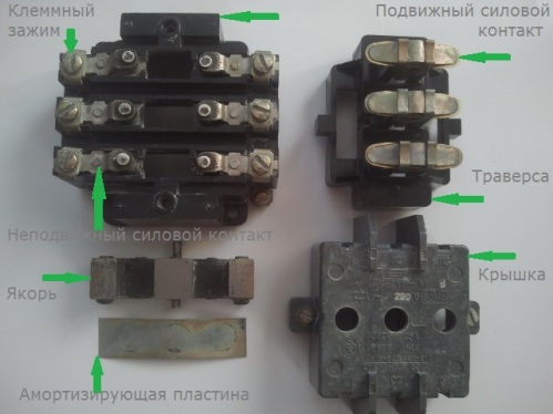
The upper part of the starter contains: a set of contacts, a moving part of the magnetic circuit with a return spring. It is needed to open the contacts, when voltage is not applied to the coil, the contacts return to their normal positions. In many instances, an arcing chamber is located in it. Read more in the article. about the device and the principle of operation of magnetic starters.
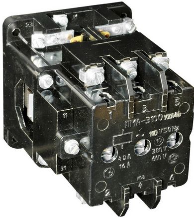
A general view of the old starter is shown above. Closer to the viewer are power contacts, they are numbered from 1 to 6. Next, we see the block contacts, they are needed for implementing additional functions of the circuit and self-pickup.
Interesting:
Starter contacts are closed only when voltage is applied to the coil. The control panels of such devices are usually equipped with buttons without locking, which means that the starter will be turned on only when you hold the button pressed.
If for some schemes this is good, for example, for hoist, winch and other lifting mechanisms, then for motors working in long-term mode this will not work, imagine a control circuit for a pump that should work without stopping.
Of course, you can use the fixed buttons and toggle switches, but the Start and Stop buttons on the remote control are more clearly used, therefore, a circuit with self-locking via block contacts is used.
Why did I start an article on modern switching devices with a consideration of the classical model? It's simple - they are still found in large numbers at enterprises, industrial facilities and others. In addition, they have a very large margin of safety, both in terms of resource and in terms of operation in overloaded modes.
The structure of modern models of magnetic starters
Let's consider not a special case, but modern devices in a general form. Individual moments may vary and depend on the specific model or manufacturer, so I will try to cover the widest possible range of information.
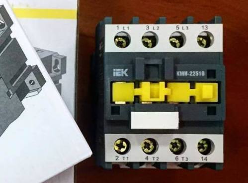
Let's start with the general view of a modern starter.
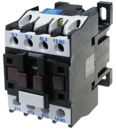
On the front part in front of us are 4 pairs of contacts. Three of them marked with type 1L1 and 2T1 are power contacts for connecting the load to a three-phase power supply. Contacts marked "L" are used to connect the power source, and "T" - to connect the consumer.
In general, you can connect the network from both the upper side (L) and the lower side (T). But compliance with the marking and connection described in the first method will make the circuit more visual and simplify its maintenance to other electricians who will work with it except you. It is customary to start power from the upper side.
A pair of 13NO-14NO contacts are self-pickup contacts, or block contacts. Their purpose is described above.
Interesting:
The main difference between modern contactors is the marking of the terminals, it must be remembered that the terminals marked "L" and "T" are used to connect power lines - power and load. Contacts marked with NO and NC are used for self-pickup and other circuit functions.In this case, NC is normally closed (closed), and NO is normally open (open).
A normal state of contacts is a condition in which there is no external influence on a button or starter, i.e. when the button is NOT pressed, and in the case of a starter, there is no voltage on the coil and it is turned off.
Such starters also consist of upper and lower parts, for a change we will consider the upper part on the example of another starter.
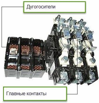
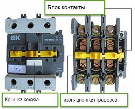
As you can see, all the component parts are the same as on the old domestic copies. However, pay attention to the yellow detail - the insulating traverse; on the previous copy it was made in brown. Firstly, by its position you can judge the state of the starter. If it is retracted, the starter is on, and if flush or slightly protrudes above the cover, it is off.
In addition, you can force it to turn on in case of problems with the coil power circuit. You just need to push the traverse with a screwdriver or something else. Be careful that you are not shocked, such switching of powerful loads, and especially motors, can be dangerous. In the absence of proper qualifications, this is not recommended.
What else do you need to know about starters?
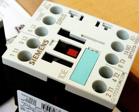
When connecting the starter, carefully check what voltage the coil is designed for. The fact is that the coils are mainly found at voltages of 220 and 380 volts, this is indicated by the corresponding designation on its case.
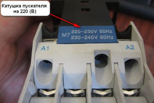
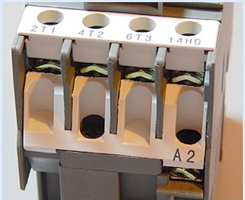
The coil contacts are labeled A1 and A2. One of the coil contacts can be duplicated on the opposite side of the starter for easy connection and assembly of the circuit. This is reflected in the picture below, pay attention from this side only one of the ends of the coil - A2.
Information on the characteristics of the starter is as follows.
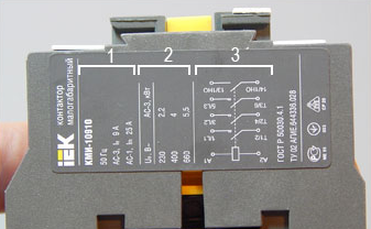
The starter cannot switch the same current for different types of load. The case may have a sticker or inscriptions with specifications.
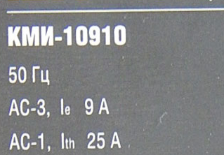
AC-3 and AC-1 are application categories, they say that an inductive load, such as an electric motor, it can switch to a current of up to 9 A, and in the case of an active load (heating elements and incandescent lamps) up to 25 A. The sticker can consist of several sectors with similar information or useful data, for example such.
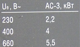
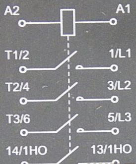
On the front panel or side can be applied to the circuit with the arrangement of contacts.
The contact diagram is implemented in this form. The names of the terminals and their position in the normal state (disconnected coil) are signed on it.
Block of additional contacts for a magnetic starter, what is it and how to use it?
The traverse has another additional function - connection with an additional contact block. Pay attention to its appearance and shape, there are hooks on its protruding part.
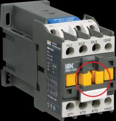
The contact block is an additional module that is mounted on top of the starter.
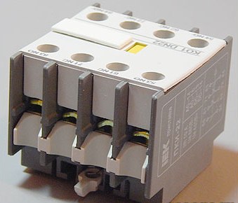
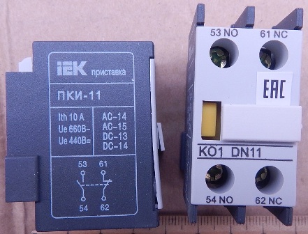
Typically, a contact block contains 2 or 4 pairs of contacts. 2 pairs are made in normally open form, and 2 pairs in closed form. These contacts can be used both for switching a low power load and for implementing additional functions.
Additional features and equipment
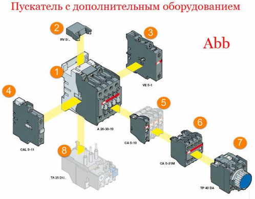
It is worth noting that, in addition to the contact block, additional equipment is connected to the starters.
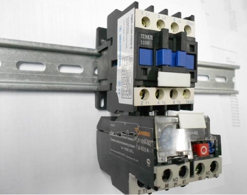
Thermal protection, additional block contacts, voltage limiters, reverse lock, start delay timer. In the picture you see additional equipment for the ABB starter.
Each of the manufacturers can produce other sets of additional devices. Engineers of large companies have provided solutions for a number of production tasks that are implemented using starters. Previously, this had to be done using separate modules, and this increased both the number of wires located in the shield for connecting operational circuits and blocks, and the total occupied space.
Magnetic starter connection diagram
I have already said that the magnetic starter is usually connected via buttons without locking. These buttons are installed in the button post. One of the most common options is a post like PKE, shown in the photo below.
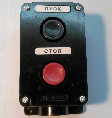
If you need to realize engine rotation in both directions, use a post with three buttons:
-
"Forward";
-
"Back";
-
“Stop” - usually red.
Inside the case, you will find the terminals on the back of the buttons, each with a pair of normally closed and a pair of normally open, located on opposite sides.
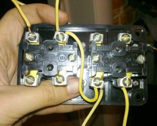
Take a look at the diagram, to connect the starter through a push-button post, the phase wire through a normally-closed pair of contacts of the stop button is connected to a normally-open pair of the start button. From the second terminal of the start button, the wire goes to the coil.
The coil at one end is connected to zero (if it is at 220 V) or to the other phase (if the coil is 380 V). And second to the wire from the start button. In this case, a normally-open pair of block contacts from the starter (the same self-pickup) is connected in parallel with the start button.
To do this, one of the contacts with a jumper is connected to the output of the coil, which is connected to the “start” button, so as not to lay an extra cable to the button post, and the second terminal of the block contact is connected to the terminal of the “start” button that is connected to the phase wire, from Stop buttons.
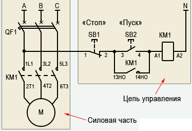
Contacts "13NO-14NO" - normally-open pairs block of contacts, in English these are those that are NO.
Only three wires are laid to the button post:
-
Phase on "STOP";
-
To the “START” button;
-
From block contacts to phase on “START” for self-pickup.
conclusions
Modern starters, although they differ in appearance and a certain functionality, however, they perform the same tasks as before. Different types of starters can be interchanged, only the current for which a specific model is designed should be provided.
See also on our website - Maintenance and repair of magnetic starters
See also at i.electricianexp.com
:

