Categories: Novice electricians, Industrial electrician
Number of views: 43810
Comments on the article: 0
Device and relay application examples, how to choose and correctly connect a relay
Switching is turning the appliance on or off in the network. To do this, use disconnectors, switches, circuit breakers, relays, contactors, starters. The last three (relays, contactor and magnetic starter) are similar in structure, but are designed for different load capacities. These are electromechanical switching devices. Beginners often have questions like:
-
“Why does the relay have so many contacts?”;
-
“How to replace the relay if there is no similar pin arrangement?”;
-
"How to choose a relay?".
I will try to answer all these questions in the article.
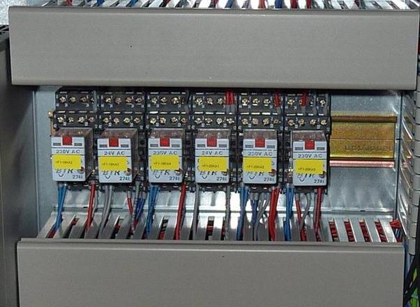
What is a relay for?
To turn on the load, you need to apply voltage to its conclusions, it can be constant and variable, with a different number of phases and poles.
Voltage can be applied in several ways:
-
Plug-in connection (insert the plug into a socket or plug into the socket);
-
Disconnector (how do you turn on the light in the room, for example);
-
Via relay, contactor, starter or semiconductor switching device.
The first two methods are limited both by the maximum switching power and by the location of the connection point. This is convenient if you turn on the light or the device with a switch or an automaton at the same time and they are located next to each other.
For an example, I will give a situation, for example water tank (boiler) - this is a fairly powerful load (1-3 kW or more). Electric power input in the corridor, and there is an automatic boiler switch on the switchboard, then you need to extend a cable with a cross section of 2.5 square meters. mm 3-5 meters. And if you need to include such a load over a long distance?
For remote control, you can use the same disconnector, but the greater the distance, the greater the resistance of the cable will be, which means that you will need to use cables with a large cross section, and this is expensive. Yes, and if the cable breaks, it’s impossible to turn on the device directly on the spot.
To do this, you can use a relay that is installed directly near the load, and turn it on remotely. You do not need a thick cable for this, because the control signal is usually from units to tens of watts, while a load of several kilowatts can be turned on.
Switches and disconnectors - needed to manually turn on the load, in order to control it automatically, you need to use relays or semiconductor devices.
Scopes of the relay:
-
Protection schemes for electrical installations. For automatic input of protection energy against low and high voltages, Current relays - for triggering current protections, permitting the start-up of electrical machines, etc .;
-
Automation;
-
Instrumentation and automation;
-
Security systems;
-
For remote inclusion.
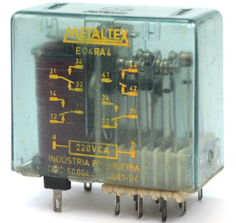
How does the relay work?
An electromagnetic relay consists of a coil, an armature and a set of contacts. The set of contacts may be different, for example:
-
Relays with one pair of contacts;
-
With two pairs of contacts (normally closed - NC, and normally open - NO);
-
With several groups (to control the load in independent from each other circuits).
The coil can be designed for different values of direct and alternating current, you can choose for your circuit so as not to use an additional source to control the coil. The contacts can switch both direct and alternating current, the current and voltage are usually indicated on the relay cover.
The load power depends on the switching ability of the device due to its design, an arcing chamber is present on powerful electromagnetic switching devices to control a powerful resistive and inductive load, for example an electric motor.
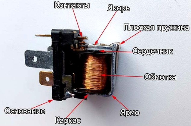
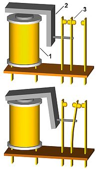
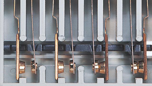
The relay is based on the magnetic field. When a current is supplied to the coil, the lines of force of the magnetic field penetrate its core. The anchor is made of material that is magnetized and is attracted to the core of the coil. Contact copper plastic and flexible eyeliner (wire) can be placed at the anchor, then the anchor is energized and voltage is applied to the fixed contact via copper buses.
The voltage is connected to the coil, the magnetic field attracts the armature, it closes or opens the contacts. When the voltage disappears, the armature returns to normal with a return spring.
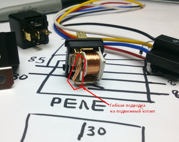
There may be other designs, for example, when the anchor pushes a movable contact, and it switches from normal to active, this is shown in the picture below.
Bottom line: The relay allows a small current through the coil to control a large current through the contacts. The magnitude of the control and switched (via contacts) voltage can be different and does not depend on each other. This way we get galvanically isolated load control. This gives a significant advantage over semiconductors. The fact is that the transistor or thyristor itself is not galvanically isolated, moreover, it is directly connected.
Base currents are part of the current switched through an emitter-collector circuit, in a thyristor, in principle, the situation is similar. If the PN junction is damaged, the voltage of the switched circuit can go to the control circuit, if it is a button, then it’s okay, and if it’s a microcircuit or microcontroller - they, most likely, will also fail, therefore additional galvanic isolation is realized through an optocoupler or a transformer. And the more details - the less reliability.
Relay Benefits:
-
simplicity of design;
-
maintainability. you can audit most relays, for example, clean the contacts from soot and it will work again, and with a certain dexterity, you can replace the coil or solder its conclusions if they come off the outgoing contacts;
-
full galvanic isolation of the power circuit and control circuit;
-
low contact resistance.
The lower the resistance of the contacts, the less voltage is lost on them and less heating. Electronic relays generate heat, a little lower I will briefly talk about them.
Disadvantages of the relay:
-
due to the fact that the design is essentially mechanical - a limited number of operations. Although for modern relays it comes to millions of operations. So the dubious moment is a flaw.
-
response speed. An electromagnetic relay trips in fractions of a second, while semiconductor switches can switch millions of times per second. Therefore, it is necessary to approach wisely the choice of switching equipment.
-
in case of deviations from the control voltage, the relay may rattle, i.e. the state when the current through the coil is small, for the normal holding of the armature, and it “buzzes” opening and closing at high speed. This is fraught with an early failure of it. The following rule follows: to control the relay, an analog signal must be supplied through threshold devices, such as Schmidt trigger, comparator, microcontroller, etc .;
-
Clicks when triggered.
Relay characteristics
To choose the right relay, you need to take into account a number of parameters, which describes its features:
1. The coil voltage. A 12 V relay will not work stably or will not turn on at all if you apply 5 V to its coil.
2. The current through the coil.
3. The number of contact groups. The relay can be 1-channel, i.e. contain 1 switching pair. Or maybe 3-channel, which will allow you to connect 4 poles to the load (for example, three phases 380V)
4. Maximum current through the contacts;
5. Maximum switching voltage. For the same relay, it is different for direct and alternating currents, for example 220 V AC and 30 V DC.This is due to the peculiarities of arcing when switching different electrical circuits.
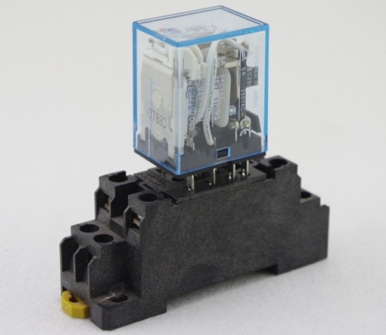
6. Installation method - terminal blocks, terminal for terminals, soldering to a board or DIN rail mounting.
Electronic relays
A normal electromagnetic relay clicks when triggered, which may interfere with your use of such devices in domestic premises. Electronic relay, or as it is also called solid state relay, devoid of this drawback, but it generates heat, because as a key, a transistor (for a DC relay) or a triac (for an AC relay) is used. In addition to the semiconductor key, an electronic relay is installed in the electronic relay to provide the ability to control the key with the desired control voltage.
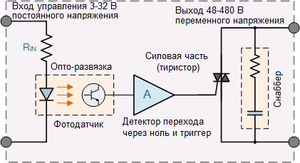
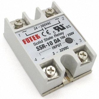
Such a relay for control uses a constant voltage from 3 to 32, and commutes an alternating voltage from 24 to 380 V with a current of up to 10 A.
Benefits:
-
low consumption of control current;
-
lack of noise when switching;
-
a greater resource (a billion or more operations, and this is a thousand times more than that of an electromagnetic one).
Disadvantages:
-
heats up;
-
may burn from overheating;
-
worth more;
-
if it burns, it will not work.
How to connect a relay?
The picture below shows a diagram of the connection of the relay to the network and the load. A phase is connected to one of the power contacts, to a second load, and zero to a second load terminal.
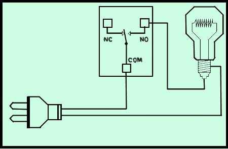
So the power unit is going. The control circuit is assembled as follows: a power source, such as a battery or power supply, if the relay is controlled by direct current, is connected to the coil through a button. To control an AC relay, the circuit is similar, an alternating voltage of the desired value is supplied to the coil.
Here it is obvious that the control voltage does not depend on the voltage in the load, also with currents. Below you see the control circuit of the activators of the central locking of the car with bipolar control.
The next task, for the activator to move forward, you need to connect the plus and minus to its solenoid in order to shift it back - the polarity must be changed. This is done using two relays with 5 contacts (normally-closed and normally-open).
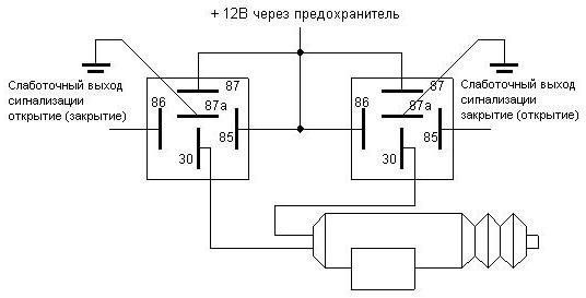
When voltage is supplied to the left relay, plus is supplied to the lower wire (according to the circuit) of the activator, through the normally-closed contacts of the right relay, the upper wire of the activator is connected to the negative terminal (to ground).
When the voltage is applied to the coil of the right relay, and the left is de-energized, the polarity is reversed: plus, through the normally open contact of the right relay, it is supplied to the upper wire. And through the normally closed contact of the right relay - the lower wire of the activator is connected to ground.
I gave this particular case as an example of the fact that using a relay you can not only turn on the voltage to the load, but also implement a variety of connection and polarity reversal schemes.
How to connect a relay to a microcontroller
It is convenient to use a relay to control the AC load through the microcontroller. But a small problem arises: the current consumption of the relay often exceeds the maximum current through the pin of the microcontroller. To solve it, you need to increase the current.
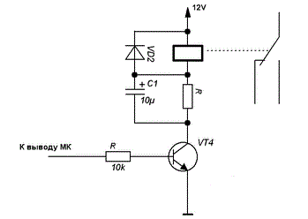
The diagram shows the connection of a relay with a 12V coil. Here, the reverse conductivity transistor VT4, it plays the role of a current amplifier, the resistor R is needed to limit the current through the base (set so that the current is no more than the maximum current through the pin of the microcontroller).
The resistor in the collector circuit is needed in order to set the coil current, it is selected according to the value of the response current of the relay, in principle, it can be excluded. In parallel with the coil, a reverse diode VD2 is installed - it is needed so that bursts of self-induction do not kill the transistor and the output of the microcontroller. With the diode, the bursts will go towards the power source, and the energy of the magnetic field will stop working.
Arduino and relays
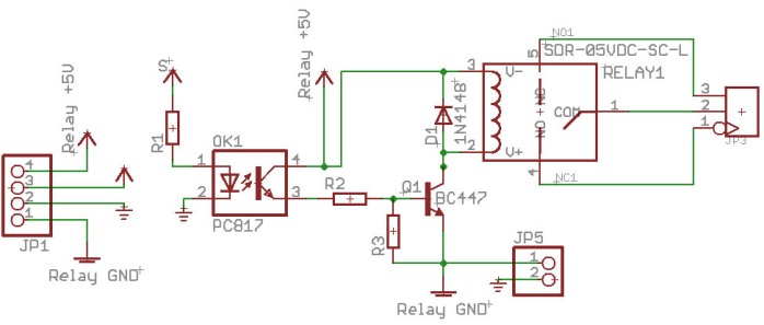
For lovers Arduino There are ready-made relay shields and separate modules.To secure the outputs of the microcontroller, depending on the specific module, optocoupler of the control signal can be implemented, which will significantly increase the reliability of the circuit.
The scheme of such a module is:
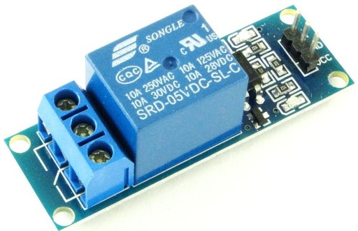
We talked about the characteristics of the relay, and so they are often indicated in the markings on the front cover. Pay attention to the photo of the relay module:
-
10A 250VAC - means that it is able to control the load of alternating voltage up to 250V and with current up to 10 A;
-
10A 30VDC - for direct current, the voltage in the load should not exceed 30V.
-
SRD-05VDC-SL-C - marking, depends on each manufacturer. In it we see 05VDC - this means that the relay will operate on a voltage of 5V on the coil.
At the same time, the relay has normally open contacts, only 1 movable contact. The Arduino connection diagram is shown below.
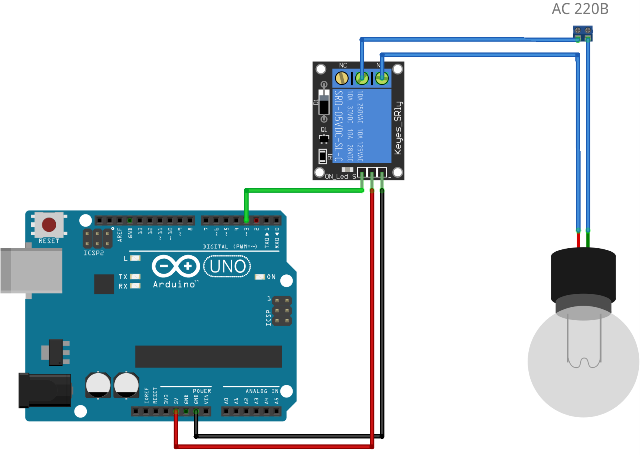
Conclusion
Relay is a classic switching device that is used everywhere: control panels in panel board industrial workshops, in automation, to protect equipment and people, to selectively connect a specific circuit, in elevator equipment.
It is very important for a novice electrician, electronics engineer or radio amateur to learn how to use relays and make circuits with them, so you can use them in work and household, implementing relay algorithms without the use of microcontrollers. Although this will increase the size, it will significantly improve the reliability of the circuit. After all, reliability is not only durability, but also reliability and maintainability!
See also at bgv.electricianexp.com
:
